262391
32
Revision A
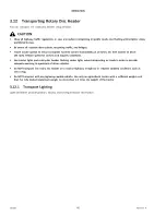
Figure 3.17: Alignment with Header Carrier Frame
2°
ϭϬϰϯϳϯϯ
A
B
C
D
E
F
7.
Adjust lower link arms (A) on the 3-point hitch until dimension (B) between the bottom of the carrier frame and the
ground is 184 mm (7.25 in).
NOTE:
The lift assist cylinders must be lowered onto downstops (F) before aligning the carrier frame.
8.
Adjust the length of top link (C) on the 3-point hitch until carrier frame angle (D) is approximately 2° forward. Use
bubble level (E), located on the right side of the carrier frame to set the angle.
ϭϬϰϯϲϯϮ
A
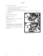
Figure 3.18: Tractor Front PTO Connection
9.
Position the driveline onto the tractor
’
s PTO shaft.
10. Pull back collar (A) on the driveline and push the driveline
onto the PTO shaft until it locks. Release the collar.


