262391
109
Revision A
1011399
B
A
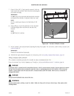
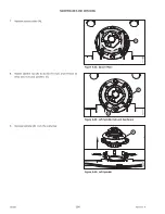
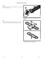
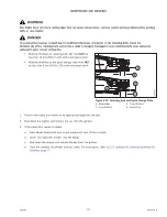
Figure 4.53: Spindle Orientation
8.
Insert studs (A) into the spindle as shown.
NOTE:
The plugs are factory-installed as shown in position (B), but
may loosen over time. Ensure that the studs are inserted
into the proper location.
IMPORTANT:
Ensure that the clockwise spindles rotate clockwise and
that the counterclockwise spindles (with machined grooves)
rotate counterclockwise.
IMPORTANT:
The offset gear design of the cutterbar makes it possible to
install spindles that rotate in the wrong direction. This will
prevent discs from spinning up after impact, resulting in
cutterbar component damage.
1030755
A
C
C
B
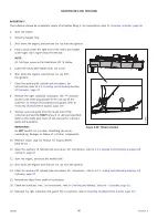
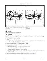
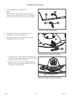
Figure 4.54: Alignment Tool
9.
Check and adjust the disc timing as follows:
NOTE:
There are an odd number of teeth on the cutterbar
gears; this can make aligning the spindle hub
challenging.
a.
Place one end of disc timing tool (A) on adjacent
disc (B) and the other end on the left spindle as shown.
b.
Check bolt hole alignment (C) as shown.
c.
If the alignment is slightly off, lift the spindle and
rotate it one tooth in either direction to try and line up
the bolt holes.
d.
Recheck the timing using the disc timing tool. If the
discs are still not lining up, lift the spindle and rotate
the hub 1/4 turn at a time. Recheck the timing using
the disc timing tool.
e.
Repeat the disc alignment procedure until the bolt
holes are aligned.
NOTE:
The arrow in the illustration points to the front of the
header.

