262391
110
Revision A
1011375
A
B
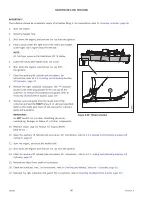
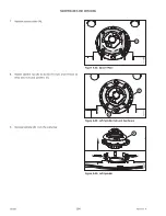
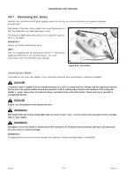
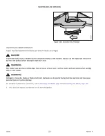
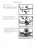
Figure 4.55: Left Spindle Hub
10. Ensure that hub (A) is fully seated into the cutterbar before
tightening nuts (B).
11. Rotate spindle hub (A) to access the studs, and install 11
M12 lock nuts (B) and washers.
1014662
1
2
3
4
5
6
7
8
9
10
11
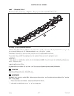
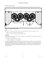
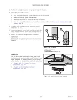
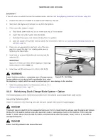
Figure 4.56: Tightening Pattern
12. Torque the bolts to 50 Nm (37 lbf·ft), following the
tightening pattern shown.
NOTE:
The hub has been removed from the illustration for clarity.
1011389
A
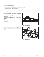
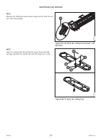
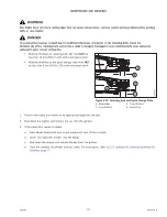
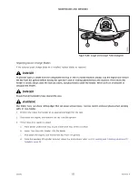
Figure 4.57: Spacer Plate
13. Install spacer plate (A).

