262391
105
Revision A
Installing Cutterbar Spindles
Ensure that the discs are timed correctly when installing the cutterbar spindles, or damage to the cutterbar may result.
1028991
A
B
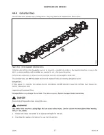
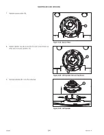
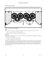
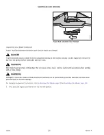
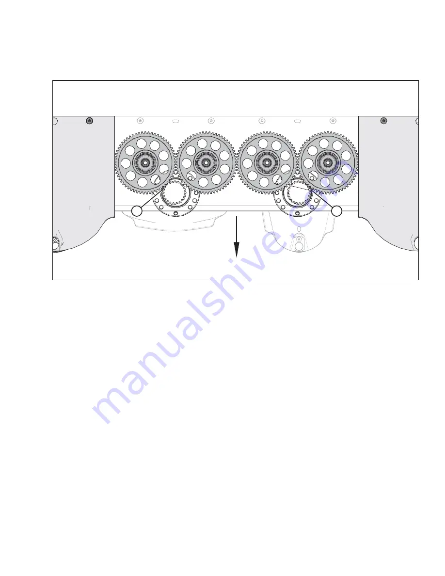
Figure 4.46: Underside of Cutterbar Spindles
NOTE:
Right discs (A) and left discs (B) are slightly offset as shown, depending on which idler gear the spindle is turning:
•
Spindles that rotate clockwise have left-leading threading
•
Spindles that rotate counterclockwise have right-leading threading
IMPORTANT:
Right discs (A) and left discs (B) are timed and must be installed at a 90° angle relative to the neighboring discs. Misaligned
discs could result in the following:
•
Disc blades of co-rotating discs hitting each other
•
Disc blades of diverging discs hitting adjacent discs
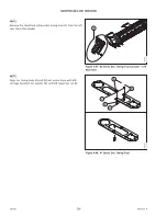
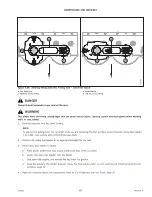
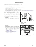
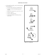
Inspect the disc timing using the disc timing tool before securing the spindle to the cutterbar. The disc is correctly timed if
the spindle hub is aligned with the disc timing tool as shown in Figure
. Turn the disc by hand to ensure that
the disc blades do
NOT
contact each other or those of adjacent discs. If the alignment is incorrect, lift the spindle clear of
the mounting bolts, rotate the spindle 180° while ensuring that the base does not turn, and reinstall the spindle. Recheck
the timing before securing the hub. Spindles do
NOT
need to be bolted to the disc timing tool; visual confirmation of the
alignment is sufficient.


