

Acceptance: DLP-501
363-205-401
Page 2 of 4
Issue 7, March 1997
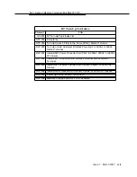
13.
NOTE:
Plug-in units are not inserted into connectors until all tests and
verifications have been completed.
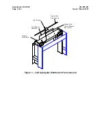
At both white and blue banks, insert channel unit in slots labeled 1/2, 23/24,
and 47/48 on shelf AB and slots 49/50, 71/72, and 95/96 on shelf CD to check
for misaligned or bowed shelves. Remove unit and proceed to Step 14.
14. Inspect for misaligned, dented, or twisted shelves.
15. Are there any misaligned, dented, or twisted shelves?
If YES, then continue with Step 15.
If NO, then proceed to Step 16.
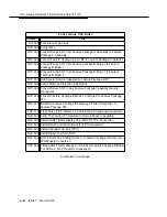
16. Resolve problems through local procedures.
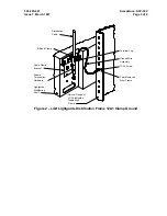
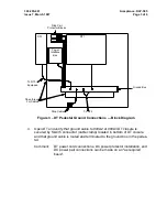
17. Verify that 3-type protectors are installed in protector panel.
18. Use special key to open electronics section of cabinet (separate electronics
section of cabinet from battery section of cabinet).
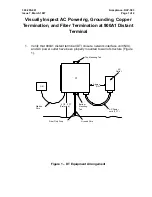
19. Verify that power and battery shelves are properly installed and tightly
secured.
20. At front of battery section of cabinet, verify that battery shelves are free from
defects (are not dented or twisted).
21. At rear of electronics section of cabinet, perform Steps 21 through 24.
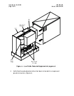
22. Verify that there is no broken or damaged equipment (connectors, wiring,
backplane wiring board, etc). Resolve problems through local procedures.
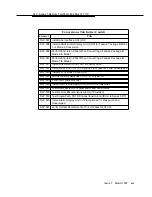
23. Verify that there are no bent, broken, or crossed terminals on backplane.
Resolve problems through local procedures.
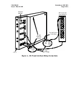
24. Verify that all cabling and wiring are terminated and tied into forms. Resolve
problems through local procedures.
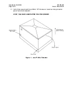
25. Verify that plastic covers are placed behind dual bank assembly and power
shelf. Resolve problems through local procedures.