background image

Installation

61

Due to our policy of continuous product innovation, some specifications may change without notice. 


©LG Electronics U.S.A., Inc., Englewood Cliffs, NJ. All rights reserved. “LG” is a registered trademark of LG Corp.

Internet Connection

Internet connection and a ThinQ service subscription are required for the 10-year limited warranty 
and to view the system status in the LG ThinQ® App.


y

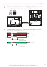
Connect the ethernet cable first, then connect the communication cable.

INFO

Ethernet Connection


y

Ethernet cable must be CAT5 UTP(24 AWG) or better.


y

If it is not possible to run an Ethernet cable directly to the customer’s network router, a Powerline 
Ethernet socket adapter may be used.


y

Fix the cable to the lower hook as shown in the figure. Arrange the cable between the plastic case 

and metal enclosure.

Содержание ESS Home 8

Страница 1: ... U S A Inc Englewood Cliffs NJ All rights reserved LG is a registered trademark of LG Corp Model LG ESS Home 8 RBA008K0A00 Home 8 RA768K16A11 Smart Energy Box REA200AP0 Please read this manual carefully before operating and retain it for future reference http www lg com us ess Copyright 2022 LGEUS All Rights Reserved R e v B 0 8 0 9 2 0 2 2 MFL71893101 ...

Страница 2: ... not throw away destroy or lose this manual Please read carefully and store in a safe place for future reference Content familiarity is required for proper installation The instructions included in this manual must be followed to prevent product malfunction property damage injury or death to the user or other people Incorrect operation due to ignoring any instructions will cause harm or damage The...

Страница 3: ...cable state local jurisdiction regulations follow the instructions in this manual and using personal protective equipment PPE All transport or handling of the LG ESS Home 8 product must be done in accordance with local safety standards Before starting the installation or commissioning of the LG ESS Home 8 read through the entire manual and take note of all precautions All U S and Canada electrical...

Страница 4: ... place or install flammable or potentially explosive objects near the product or in explosive atmospheres y y Do not charge or discharge arbitrarily It may lead to fault electric shock or burns y y Do not damage the unit in any manner such as by dropping deforming impacting cutting or spearing with a sharp object It may cause electrolyte leakage or fire y y Breakdown of the unit may cause electrol...

Страница 5: ...e package containing the ESS and accessories Therefore special care must be taken in handling Make sure to use the handle lift to deliver and install the package y y Do not open or damage batteries Released electrolyte is harmful to the skin and eyes It may be toxic y y Do not place heavy objects on this product It may cause deformation or fracture y y Do not place any kind of objects on top of th...

Страница 6: ...s pipes y y Do not put the product or components in water or liquid y y Make sure that there are no water sources such as faucets or sprinklers near the installation site y y Do not block any ventilation openings Ensure reliable operation of the product and protect it from overheating Do not block any openings by placing objects on this product y y The metal enclosure may heat to a high temperatur...

Страница 7: ...uickstart y y If the S W version is not up to date during installation update the S W using a FAT32 formatted USB storage device When the SE Box is connected to Ethernet through a LAN cable after normal operation it is automatically updated to the latest S W version y y Handling of batteries should be performed or supervised by a trained service provider y y The battery does not discharge when the...

Страница 8: ...dical attention In case of ingestion Induce vomiting and seek medical attention Fire Fighting Measures Suitable extinguishing media Use metal fire extinguishing powder or dry sand if only a few cells are involved In case of a large fire use a large amount of water to extinguish Special hazards arising from the chemical May form hydrofluoric acid if electrolyte comes into contact with water In case...

Страница 9: ...ation 27 Installation Location 28 Distance Between Components 30 Minimum Clearance 31 Floor Standing Wall Support 33 Mounting the Home 8 33 Mounting the SE Box 38 Connections 41 Whole Home Backup Service Equipment 41 Service Equipment Preparation If Required 42 Wiring Connection between the SE Box and Home 8 45 Grid and Load Connections 53 Connect to PV Inverter 57 Internet Connection 61 External ...

Страница 10: ...inQ 113 Using LG ThinQ 114 Troubleshooting Error Codes and Messages 116 PCS Error Codes 116 SE Box Error Code 118 Battery Error Code 119 Appendix Black Start 123 Maintenance 124 Cleaning the Product 124 Inspecting Regularly 124 Shutting Down the System 124 Disposing the product 125 Compliance Information 126 Specifications 128 Compatible Eaton Parts 133 Multiple Home 8 Units or PV Inverters Connec...

Страница 11: ...all functions smoothly users must connect this product to the Internet and subscribe to the LG ThinQ service Data Line Alternative Current Direct Current PV Module Air Conditioning Washing Machine HVAC Electric Vehicles Oven TV Refrigerator Heater LED Lighting Grid Utility Utility Meter PV inverter1 optional Mobile Phone LG ThinQ SE Box Home 8 1 PV inverter is NOT PROVIDED by LG Electronics y y Al...

Страница 12: ...e load consumption characteristic and the preferred operation of the home Please contact an authorized dealer or the seller for more details System configuration Whole Home backup Partial Home Backup SE Box Utility Meter Main Panel Backup PV inverter Home 8 SE Box Utility Meter Sub panel Backup PV inverter Home 8 Main Panel Non Backup Product Specifications All specifications and descriptions cont...

Страница 13: ...ed for connection to an external conductor for protection against electrical shock in case of a fault or the terminal of a protective earth ground electrode Read the instruction manual booklet before starting work or before operating equipment or machinery Caution risk of danger Caution hot surface Caution risk of electric shock energy storage timed discharge Caution risk of electric shock No open...

Страница 14: ...o put out flames Ensure the conductive terminals are matched to their corresponding counterparts Abbreviations in this Manual Abbreviation Designation Explanation ESS Energy Storage System Inverter system that stores energy in a battery and uses it Home 8 All In One unit Battery integrated PCS SE Box Smart Energy Box Micro grid interface device that consist of an ATS automatic transfer switch ener...

Страница 15: ...nic system that control a rechargeable battery system for securing battery safety DC Direct Current AC Alternating Current DHCP Dynamic Host Configuration Protocol Standardized network protocol used on Internet Protocol IP networks for automatic distributing network configuration parameters such as IP addresses for interfaces and services LAN Local Area Network A network that interconnects compute...

Страница 16: ... a registered trademark of LG Corp Unpacking Unpacking the SE Box Unpack the SE Box from its packaging Take care when moving or installing the SE Box It may cause injury due to the weight At least 2 people are needed for safe installation and moving WARNING a Remove the package banding and open the box b Take out all the accessories and components c Pull out the SE Box from the package ...

Страница 17: ...lift does not move when standing the product on the lift y y When moving the product using a lift secure the product using a belt etc WARNING Be careful not to damage Home 8 when standing the product on the hand lift The cut out part at the bottom of the box can be used to prevent scratches by inserting it between the product and the hand lift INFO a Remove the package banding and open the box Tak...

Страница 18: ...LG Electronics U S A Inc Englewood Cliffs NJ All rights reserved LG is a registered trademark of LG Corp If the installation location has excessive presence of insects block the vent hole with the Vent Plug if needed INFO c Put the hand lift into the bottom of the package and stand the Home 8 upright on the hand lift ...

Страница 19: ...nics U S A Inc Englewood Cliffs NJ All rights reserved LG is a registered trademark of LG Corp Home 8 Contents Home 8 1EA Wall bracket 2EA Communication terminal block 2EA Vent plug SE Box Contents SE Box Quick Installation Guide Mount Hole Guide 200A CT for PV CT harness N GND bonding busbar O rings 4EA CT terminal block 2EA ...

Страница 20: ... to 1 5 m Drill and drill bit Torque wrench with hex socket M5 1 4 inch M6 3 8 inch M8 5 16 inch Screw driver Phillips 5 mm Flat head 6 5 4 2 mm Hex wrench 6 mm 1 4 inch 8 mm 5 16 inch 14 Inclinometer Tape measure Writing utensil Cutter RJ 45 climping tool Wire strippers A Wire strippers B Wire strippers C Wire cutter A Wire cutter B Spanner 17 mm 21 32 inch Ring terminal crimping tool optional Th...

Страница 21: ...unding Cable for Home 8 connection Minimum 600 V rated copper Cu cable rated at 90 C 194 F 6 4 AWG BLACK WHITE RED 8 6 AWG GREEN Follow NEC and local codes y y Power and Grounding Cable for SE Box connection Minimum 600 V rated copper Cu or aluminum Al cable rated at 90 C 194 F or better 6 AWG 250 kcmil BLACK WHITE RED 14 AWG 2 0 AWG BLACK WHITE RED GREEN or Bare Follow all NEC and local codes y y...

Страница 22: ...l rights reserved LG is a registered trademark of LG Corp Part Names Front and Rear Home 8 A B C H D E Front Rear G F A LED Indications B Conduit knockout C POWER button Push type ON OFF toggle button D BLACK START 6s button Momentary type press and hold for 6 seconds E Front cover F Height leveling adjustable leg G Ventilation opennings H Bracket connected parts ...

Страница 23: ...f death or serious injury due to electric shock Before working on any Home 8 wiring make sure the Home 8 battery circuit breaker is set to OFF WARNING 1 2 1 2 PCS Battery A B E F G H D C A DIP switches B AC power terminals L1 Neutral L2 CN_GRID C Communication terminal block to another Home 8 CN_PCS D Communication terminal block to the SE Box CN_ATS E Ground terminal Protective Earth terminal AC ...

Страница 24: ...tions Home 8 LED Status and Indications PV Green Off Red Blink Error code Generating Not generating SE Box Fault Grid Green Off Red Blink Error code Normal Abnormal PCS Fault Gateway On Off Red Blink Error code Connected Not Connected Battery Fault SoC level Remaining time hr Error code On Grid Backup operation Fault Charge On Off BAT Charging Not operating Discharge On Off BAT Discharging Not ope...

Страница 25: ...G Electronics U S A Inc Englewood Cliffs NJ All rights reserved LG is a registered trademark of LG Corp Front and Rear SE Box A B C D E Front Rear F G Bottom A Front cover B Cover lock C Conduit knockout right D Wall support screw holes 4 points E Conduit knockout left F Conduit knockouts bottom G Conduit hole bottom ...

Страница 26: ...ox A B C D E G F H I J K L M A Communication terminal to Home 8 CN1000 B Panelboard C Backup load terminals L1 D Backup load terminals L2 E Neutral terminals for grid and load F HMI Human Machine Interface display G Grid terminal L2 H Grid terminal L1 I Neutral terminals for Home 8 and PV inverter J Non backup load terminals L2 K Non backup load terminals L1 L Ground terminals for grid and load M ...

Страница 27: ...to Front and Rear Home 8 and Front and Rear SE Box 3 Plan the Conduit or Raceway y y Depending on the cable size and local code requirements select the proper Conduit or Raceway size and amount y y When installing a conduit or raceway as needed the conduit adapter must be attached to the inlet of the wiring compartment y y Conduit adapters are required for all installations and NEMA Type 3R condui...

Страница 28: ... Reduction in performance performance warranty and possible damage of the battery y y Install the unit considering the possibility of strong winds or earthquakes y y The system should be installed according to NFPA 855 y y Do not install the product in a place where it is exposed directly to ocean winds Sea salt in the air may cause the product to corrode y y If the installation site is an area wi...

Страница 29: ...e product approx 165 kg 364 lbs y y Do not install the product on the ceiling y y Do not install the product widthwise or install on a wall with a lean of more than 10 degrees y y Do not install the product tilting forward 3 000 m 9842 ft y y This product must be installed or used at an altitude of less than 3 000 m 9 842 ft y y Do not install this product in an area prone to flooding 95 y y Do no...

Страница 30: ...let Do not place any object near the air outlet Distance Between Components Follow the table below for the maximum available length between system components Wire gauge must meet local codes and in some circumstances wire gauge requirements may change based on length Types of Connections Maximum Cable Length SE Box to Home 8 Power Max 30 m When multiple Home 8 units are installed this max value is...

Страница 31: ...her devices Keep at least a 700 mm 28 inches distance between the front door and any obstacles in order to allow space for installation and servicing If the door is closed all other products should be at least 305 mm 12 inches from the front door for safety operation Ensure that the distance between the wall and Home 8 is at least 25 mm 1 inch Be sure not to place any object on top of the Home 8 t...

Страница 32: ...ange without notice LG Electronics U S A Inc Englewood Cliffs NJ All rights reserved LG is a registered trademark of LG Corp When installing the Home 8 next to an air conditioner outdoor unit install the Home 8 in a position that avoids any hot air expelled from the air conditioner outdoor unit ...

Страница 33: ...te for the wall type y y Make sure the pilot hole size matches the anchor type y y The weight of the Home 8 is 163kg 359 lbs and the SE Box is 25 kg 55 lbs The wall must contain blocked studs that can bear the weight and are of masonry or other suitable structures CAUTION y y When attaching the wall bracket to a wall adjust the horizontal level using an inclinometer or a leveler y y When indicatin...

Страница 34: ...ll which meets every installation condition and clearance requirement Indicate the positions to drill using a pencil or other writing utensil Drill holes in the indicated positions It may help to use the true to scale print of the actual wall bracket which provides the hole positions included in the package Refer to Mounting details for wall brackets for more information 406 mm 16 inches 305 mm 12...

Страница 35: ...ome 8 is very heavy Serious injury may occur due to the heavy weight when mounting it to the wall Therefore special care must be taken in handling Make sure to use the lift instead of using human strength when installing y y When hanging the Home 8 on the wall bracket slowly lower the Home 8 and make sure the Home 8 is properly mounted on the wall bracket y y If 4 points on the wall brackets both ...

Страница 36: ...odule and wiring Special care must be taken when working on a Home 8 connection y y High voltage may be energized inside the safety cover Do not open the safety cover of the Home 8 WARNING D Install a conduit as needed and attach the conduit adapter to the inlet of the wiring compartment The wiring compartment inlet accepts a standard 1 5 inch conduit adapter The following is an example of possibl...

Страница 37: ...ng codes for the appropriate fastener y y Below are the minimum guidelines for mounting and are not guaranteed to ensure profer mounting y y Screws must be placed balacned in each corner y y Ensure that the screw positions are at the center of the studs when anchoring to studs INFO Wall Type Screw Length Minimum Number of screws Wood Studs M8 5 16 inch Lag screws with washers 76 mm 3 inches 8 Conc...

Страница 38: ...s NJ All rights reserved LG is a registered trademark of LG Corp Mounting the SE Box a Use a 8 mm 5 16 inch hexagon wrench to open the door Then remove the safety cover s 4 screws using a Phillips screwdriver When opening the door do not use any tool other than an 8 mm hexagon wrench and do not apply too much force It may cause the lock to break CAUTION ...

Страница 39: ...d in the package The following is an example of possible conduit installations Depending on the site the required conduits and knockout position of the SE box would vary 400 mm 15 8 inches 500 mm 19 7 inches 520 mm 20 5 inches 600 mm 23 6 inches 1 478 mm 58 2 inches From floor y y Take care in holding the product when mounting the SE Box as it is heavy It may cause injury y y Do not hold the door ...

Страница 40: ...unting screws The mounting screws should be chosen considering the O ring The internal diameter of the O ring is the 8 mm 5 16 inches y y Adjust the horizontal level using an inclinometer or a leveler when attaching the SE Box to a wall before fixing the screws y y Depending on the surface different screws and anchors may be required for installing SE Box Therefore these screws and anchors are not...

Страница 41: ... without notice LG Electronics U S A Inc Englewood Cliffs NJ All rights reserved LG is a registered trademark of LG Corp Connections Whole Home Backup Service Equipment PV power measuring CT Main panel with main breaker Backup Utility Meter Main bonding conductor Home 8 SE Box PV inverter L1 L2 N G ...

Страница 42: ...red for safe operation of the system and for compliance with local code requirements If the system is installed as service equipment connect the Neutral and Ground terminals on the SE Box using the provided N GND bonding busbar Cross sectional area 45 mm2 a Remove the two nuts positioned in the figure b Assemble N GND bonding busbar on Neutral and Ground terminals and fasten the two nuts 10 mm hex...

Страница 43: ...d L2 lugs on the supply side using a 10 mm hex socket wrench b Install a compatible main breaker by fastening the 2 nuts L2 L2 L1 L1 10 mm hex 75 kgf cm 65 lbf in torques Before mounting a main breaker in an electrical system make sure there is no voltage present where work is to be performed The voltage in energized equipment may cause injury or death WARNING y y Main breaker terminal insulators ...

Страница 44: ...circuit breaker to comply with NEC and the local code This hold down kit can be used in placement of a c only Use d e placements stainless steel screws with when the sub feed lug block may be needed to install multiple Home 8 units and PV inverters It is recommended that the terminal of the lug block should head to the right in consideration of wire bending space Do not connect the load to the int...

Страница 45: ...tions and NEMA Type 3R conduit adapters are needed when installing outdoors One for each used conduit opening y y Required when torqueing connections Follow NEC 2017 110 14 D A well calibrated torque tool must be used to achieve the indicated torque values Use tamper proof torque mark paint after torquing connections y y Class 1 wiring methods are to be used for field wiring connections to termina...

Страница 46: ...FF If the circuit breaker is ON death or serious injury may occur due to electric shock y y High voltage is energized through the internal battery module and wiring Special care must be taken when working on a Home 8 connection y y High voltage may be energized inside the safety cover Do not open the safety cover of the Home 8 WARNING b Remove the screws on the right side and open the front cover ...

Страница 47: ...ered trademark of LG Corp c Pass the 6 conductor communication cable and the AC power conductors L1 L2 Neutral and Ground through the conduit installed between the Home 8 and SE Box L1 Black L2 Red N White G Green Com Gray d Strip off the AC power conductors L1 L2 Neutral and Ground on both the Home 8 and SE Box sides as shown in the figure below 18 mm 0 7 inch 6 4 AWG 8 6 AWG 13 mm 0 5 inch ...

Страница 48: ...ered trademark of LG Corp e On the Home 8 side connect the AC conductors to the corresponding terminals as shown in the figure below There are two ground terminals on the Home 8 side Connect the AC power ground to the upper ground terminal The ground terminals are identified with the following symbol 1 2 L1 Black L2 Red N White G Green Flat head screwdriver 6 4 AWG 52 kgf cm 45 lbf in torque ...

Страница 49: ...ion tape as shown in the figure When taping the communication wire wrap the remaining wire and cover it with insulation tape Connect the 6 conductor communication wires to the communication terminal block as shown 8 mm 0 3 inch 50 mm 2 inches 80 mm 3 2 inches 1 CAN HI 2 CAN LOW 3 12V 4 RELAY CHECK 5 GRID CHECK 6 GND Blue Green Blue White Green White Orange White Orange Drain wire 80 mm 3 2 inches ...

Страница 50: ...rain wire to the lower ground terminal as shown in the figure 1 2 Communication terminal block CN_ATS CN_PCS When you install multiple Home 8 units the DIP switch settings on each Home 8 should be different CAUTION i Set the terminating resistor for CAN communication by using a DIP switch When multiple Home 8 units are installed this terminating resistor should be ON in the last Home 8 in the dais...

Страница 51: ...l a 40A circuit breaker in the Home 8 as shown in the following figure k On the SE Box side connect the AC conductors to the corresponding terminals as shown in the figure L1 Black L2 Red N White G Green From Home 8 Flat head screwdriver Depending on wire size Follow the guide from the Eaton BR series Flat head screwdriver 2 2 0 AWG 58 kgf cm 50 lbf in torque 6 4 AWG 52 kgf cm 45 lbf in torque 14 ...

Страница 52: ...unication cable on the SE Box side insert the wires into the 6 position connectors as shown in the figure Fix the cable in the upper hook as shown in the figure Arrange the cable between the plastic case and metal enclosure Cut back the drain wire and shield The drain wire should be terminated at the Home 8 chassis ground terminal only 1 CAN HI Orange White 2 CAN LOW Orange 3 12V Green White 4 REL...

Страница 53: ...ing the proper torque tool tighten the lugs according to the table on the following page INFO a Connect the grid conductors L1 L2 Neutral and Ground to grid terminals in the SE Box as shown in the following figure When a main breaker is required install the main breaker ahead of wiring connection Please refer to SE Box Main Breaker Installation Follow the local code L1 Black L2 Red N White G Green...

Страница 54: ...kup Load L1 Black L2 Red N White G Green 5 6 inch Hex 317 kgf cm 275 lbf in torque Flat head screwdriver 2 2 0 AWG 58 kgf cm 50 lbf in torque 6 4 AWG 52 kgf cm 45 lbf in torque 14 8 AWG 40 kgf cm 35 lbf in torque There are 6 conduit knockouts on the left right and bottom of the SE Box Select the appropriate conduit knockouts and grounding location so that the cables are not twisted Knockout Positi...

Страница 55: ...200A Connect the non backup load conductors L1 L2 Neutral and Ground from the non backup panel to the SE Box non backup load terminals as in the following figure From Non backup Load L1 Black L2 Red N White G Green 5 6 inch Hex 317 kgf cm 275 lbf in torque Flat head screwdriver 2 2 0 AWG 58 kgf cm 50 lbf in torque 6 4 AWG 52 kgf cm 45 lbf in torque 14 8 AWG 40 kgf cm 35 lbf in torque There are 6 c...

Страница 56: ...ol Size Strip Length Torque Grid lug L1 L2 6 AWG 300kcmil 1 4 inch Hex 32 mm 1 25 inches 288 kgf cm 250 lbf in Non Backup Load Lugs L1 L2 6 AWG 250 kcmil 5 6 inch Hex 32 mm 1 25 inches 259 kgf cm 225 lbf in Backup Load Lugs L1 L2 6 AWG 250 kcmil 5 6 inch Hex 32 mm 1 25 inches 317 kgf cm 275 lbf in Large Neutral Lugs 6 AWG 250 kcmil 5 6 inch Hex 32 mm 1 25 inches Medium Neutral Lugs 14 AWG 2 0 AWG ...

Страница 57: ... Watt functions y y Make sure the PV inverter is a product that satisfies UL1741SA or UL1741SB y y Make sure that the Frequency Drop or Frequency Watt function is enabled in the PV inverter configuration y y If the PV inverter does not support this function or the function is turned off the product may malfunction during the backup operation y y A PV inverter that does not support a Frequency Drop...

Страница 58: ...gh the 200 A CT as shown below The side with the markings P1 and K on the CT faces the PV inverter and the side with the L and P2 faces the SE Box PV inverter L1 L2 y y Make sure the CT sensor s direction is correct y y Fix the CT sensor and the L1 cable with a cable tie and position the CT sensor inside of the SE Box CAUTION Make sure the CTs are facing the proper direction as described in this m...

Страница 59: ...nal S1 Black PV L1 S2 White PV L1 Ring terminal stud size 1 4 inch wire range 18AWG By using the sealable covers included in the CT packaging box protect screw terminals to always assure the best safety Refer to the manual included in the CT package to assemble the sealable covers d After connecting the end of the CT Harness to pins 1 and 2 of the terminal block for PV CT in the SE Box respectivel...

Страница 60: ...ange the power cables between the plastic case and metal enclosure and fasten them at the point indicated by the arrow using a cable tie From the PV Inverter L1 Black L2 Red N White G Green Flat head screwdriver Depending on wire size Follow the guide from the Eaton BR series Flat head screwdriver 2 2 0 AWG 58 kgf cm 50 lbf in torque 6 4 AWG 52 kgf cm 45 lbf in torque 14 8 AWG 40 kgf cm 35 lbf in ...

Страница 61: ...red for the 10 year limited warranty and to view the system status in the LG ThinQ App y y Connect the ethernet cable first then connect the communication cable INFO Ethernet Connection y y Ethernet cable must be CAT5 UTP 24 AWG or better y y If it is not possible to run an Ethernet cable directly to the customer s network router a Powerline Ethernet socket adapter may be used y y Fix the cable to...

Страница 62: ...nstallations NEMA Type 3R conduit fittings hubs are required when installing outdoors One for each used conduit opening y y Before working with a hole saw clear a space in the conduit area It may cause damage to cables WARNING This section provides guidelines on system functionality Please consult your local AHJ or Utility before use INFO The External Shutdown Switch is wired through a low voltage...

Страница 63: ...or an Emergency Stop Unit y y Must have an ON OFF position y y Must have a clear ON OFF position indicator y y Must be rated for outdoor use NEMA 3R or higher y y Should be installed externally in a readily accessible location preferably by the utility meter y y The maximum length of the low voltage wire running from the switch to the SE Box should not exceed 300 feet 90 m y y Should observe 12V 0...

Страница 64: ... shutdown switch will make the system operate as stated in the following table Shutdown Switch Home 8 Operation Plunger Type Mushroom Rotary Type Pressed OFF position All Home 8 operations will be shut down The Home 8 will be in standby mode with no AC voltage output This operation is the same regardless of AC grid presence Released ON Position AC grid present The system operation will resume norm...

Страница 65: ...ystem Please be careful to use the battery system in backup operation by referring to the following table Classification Types of Loads General appliance Small plug in appliance such as TVs Laptops PCs Radios Routers and Mobile chargers Lightings Compact fluorescent or LED recommended Refrigerator and freezers Small kitchen appliances Coffee makers Cookers Microwaves Large load AWHP Air to water h...

Страница 66: ...utes It may generally take 2 minutes for a single ESS installation If the system does not restart within 10 minutes please turn on the dedicated breaker of the SE Box or the Service Disconnect Switch and check the event history E If it works normally please connect the system to the grid connection by turning on the dedicated breaker of the SE Box or the Service Disconnect Switch for the grid reco...

Страница 67: ...nected to the backup load please perform backup testing without the air conditioner connected Please turn off the air conditioner circuit breaker and then do a backup testing again If the system operates well a soft starter should be installed for the air conditioner 2 Pumps Well pumps Sump pumps Pool pumps etc If the pumps were connected to the backup load please check it through the same method ...

Страница 68: ... secure and properly sealed c Arrange the communication and AC power wires neatly inside the Home 8 wiring compartment d Install the SE Box safety cover and secure it firmly with the original screws Before attaching the safety cover to the SE Box remove the panels on the circuit breaker installed positions When removing the panels make sure the burr parts in each panel hole are cleanly removed The...

Страница 69: ...nergized through the internal battery module and wiring Special care must be taken CAUTION f Switch the battery circuit breaker on the Home 8 to the ON position and close the front cover When closing the front cover make sure the front cover is securely fitted to the gasket for a proper waterproof seal 1 2 OFF ON Make sure the door is correctly closed and all bolts are fastened Otherwise the NEMA ...

Страница 70: ...ed in the SE Box or upstream of the SE Box INFO h Switch the main circuit breaker for the SE Box to the ON position and wait until the main screen appears on the HMI display It will take about 30 seconds i Switch the circuit breaker for the Home 8 to the ON position j Switch the circuit breaker for the PV inverter to the ON position if equipped k Press the POWER button and press and hold the BLACK...

Страница 71: ...rp All covers must be correctly reassembled Otherwise the NEMA 3R grade cannot be maintained CAUTION l Close and lock the front door using an 8 mm 5 16 inch hex wrench When closing the SE Box front door check the direction of the locking rack If the direction of the locking rack is not correct the door will not close properly m Set all of the system settings on the HMI display of the SE Box and st...

Страница 72: ...D CHECK LOGIC Blue White CAT 5E STP 24 16 AWG f GND Blue CAT 5E STP 24 16 AWG g Cable Shield Drain Wire Terminate at the Home 8 chassis ground lug only h L1 Line 1 Black 6 4 AWG i N Neutral White 6 4 AWG j L2 Line2 Red 6 4 AWG k Chassis Ground Lug Green Yellow 8 6 AWG y y Depending on the local code for installation methods and cable sizing calculations y y If a communication cable may use cable t...

Страница 73: ... Grid Load 6 Positions Green Bare 14 AWG 2 0 AWG c Backup Load Terminal L1 L2 Black Red 6 AWG 250 kcmil d Neutral Terminals Grid Load White 6 AWG 250 kcmil e Neutral Terminals Home 8 PV Inverter White 14 AWG 2 0 AWG f Ground Terminal Home 8 PV Inverter 6 positions Green Bare 14 AWG 2 0 AWG g Non Backup Load Terminals L1 L2 Black Red 6 AWG 250 kcmil h N GND Bonding Busbar Included with the SE Box 4...

Страница 74: ...is case other spaces on the internal panelboard can not be used for the circuit breaker Leave no breakers The Home 8 connection to the SE Box always requires a 40 A Circuit breaker This breaker serves as circuit protection for the Home 8 Breaker sizing connection and installation must comply with the National Electric Code For more information please refer to Internal Panelboard and Additional Fas...

Страница 75: ...G b RS485 1 A HIGH Red 24 16 AWG c RS485 2 B LOW Black 24 16 AWG d RS485 2 A HIGH Red 24 16 AWG e STOP_P Black 18 16 AWG f STOP_N White 18 16 AWG g AUX1_P Black 18 16 AWG h AUX1_N White 18 16 AWG i AUX2_P Black 18 16 AWG j AUX2_N White 18 16 AWG Home 8 No Terminals Recommended Wire Color Wire Gauge a CAN CAN HI Orange White CAT 5E STP 24 16 AWG b CAN CAN LOW Orange CAT 5E STP 24 16 AWG c 12V Green...

Страница 76: ...b Ext site net CT L1 White 18 14 AWG c Ext site net CT L2 Red or Black 18 14 AWG d Ext site net CT L2 White 18 14 AWG y y If external site net metering CTs are required refer to Usage of External CTs for the exact wiring requirements for external site net metering Home 8 SE Box Wiring PV Generation Metering CT Connector No Terminals Recommended Wire Color Wire Gauge e PV CT L1 Black 18 14 AWG f PV...

Страница 77: ...her power cables VFDs Variable Frequency Drives and other heavy machinery y y Do not run cables in parallel with other power cables Specific guidelines and requirements y y Use the same wire type and gauge to match that of the CTs The provided CT cable uses UL1015 18 AWG y y The extension cable pair must be twisted about one twist per inch The twisted cable increases the cable s differential immun...

Страница 78: ...nnel Before starting the SE Box settings the physical connection and installation must be securely done exactly as described in this manual y y Touch operation may not be possible when wearing gloves y y Touch operation may not work if your fingers are wet or sweaty INFO Step 1 Country And Language Settings You can choose the country and language to use for the system settings Country Press the cu...

Страница 79: ...ettings for more information Wired If the network is connected by an ethernet cable select Wire in the Network Type wizard Wireless If you want to use the wireless network connection select Wireless in the Network Type wizard Skip Internet Settings If you do not want to connect the system to the internet select Skip Internet Settings in the Network Type wizard If the system is not connected to the...

Страница 80: ...t be at least 8 characters long The password must contain at least one number one special character and one letter Press the Confirm Password field and input your password again then press Apply to set the password Step 4 System Information You can check the system information Check that the loaded system information is correct If it is not check the DIP switches on each Home 8 and press Rescan to...

Страница 81: ...Step 5 Firmware Update You can update the firmware of the system to the latest version via USB The current version and new version of the system firmware are displayed Connect a USB storage device containing the latest software to the USB connector and press Firmware update to start the firmware update Step 6 Date Time Settings You can set the current date and time Refer to Date Time Settings for ...

Страница 82: ... trademark of LG Corp Step 7 Additional System Information You can input the system name and installation date Step 8 Utility Information You can set up a communication connection with utility company and grid profile Utility Company Input the name of a utility company Grid Profile Select the appropriate grid profile option for the system environment Select the grid profile at your location ...

Страница 83: ...e Range 110 110 120 110 110 120 Trip Time Range sec 13 1 13 13 1 13 UV Level1 Voltage Range 88 0 88 88 50 88 Trip Time Range sec 21 21 50 21 21 50 OV Level2 Voltage Range 120 120 Trip Time Range sec 0 16 0 16 UV Level2 Voltage Range 50 0 50 50 Trip Time Range sec 2 2 21 1 5 0 5 21 UV Level3 Voltage Range 50 0 50 50 Trip Time Range sec 2 2 21 1 5 0 5 21 Frequency HF Level1 Frequency Range Hz 61 2 6...

Страница 84: ... information for the PV inverter that is connected to the system If you are using a PV inverter set this option to Use and fill the PV Rate Output Power and Installed PV Panel Capacity fields Step 10 External Device If you are using an external shutdown switch set the External Shutdown Switch option to Installed You can check the device that are connected to port 1 and port 2 If no devices are con...

Страница 85: ...nics U S A Inc Englewood Cliffs NJ All rights reserved LG is a registered trademark of LG Corp Step 11 Operating Mode You can select an operating mode Refer to Operating Mode for more information Step 12 Battery Settings You can set the battery s reserve SoC level in case of a power outage The default level is set to 20 ...

Страница 86: ... is a registered trademark of LG Corp Step 13 Summary This is the last stage of the settings Before operating the system check all of the settings on the Summary display Before operating the system running a Commissioning Test is a way to verify that the system has been set up correctly If it is not possible to run a Commissioning Test select Start System to launch the system ...

Страница 87: ...several settings and other information on the HOME screen A B C E D a Displays the sub menu b Displays the currently running mode c Displays the system status Waiting Charging Discharging Warning Fault Standby Stop Disconnected or Force Stop d Displays the charge status of the battery e You can check the power flow and error messages for the PV Battery Grid and Home load If there are 2 or more Hom...

Страница 88: ...the current error information is displayed in the Event History Press 6 to show the errors Type shows the severity of the error Device shows the information of the device where the error occurred and Code shows the error code Backup History If the system is in backup mode due to a power outage you can check the time when the backup started the time the power outage ended and how long the power out...

Страница 89: ...ettings The installer or user may need to change the system settings even if all of the settings were set when the system was initially installed Press to enter either the User or Installer settings menu To enter the Installer settings menu you need to input the password on the screen Input the password to enter the settings menu If you input the incorrect password 5 times you cannot attempt to in...

Страница 90: ...notice LG Electronics U S A Inc Englewood Cliffs NJ All rights reserved LG is a registered trademark of LG Corp General Settings Country Press the currently selected country and select the desired country to change Language Press the currently selected language and select the desired language to change ...

Страница 91: ...rk is connected by an ethernet cable select Wired on the Network Settings screen If the IP Settings option is set to DHCP the system will automatically be allocated an IP address from the local area network LAN through the wired connection You may need to set the network connection manually depending on the network conditions In this case press DHCP to change to Static If you set the IP Settings o...

Страница 92: ...g all the fields tab Connect to finish the wireless network connection LG SE Box provides both wired and wireless internet connection Depending on the SE Box location and the router the wireless signal may be too weak to connect to the internet The HMI screen on the SE Box will display a warning sign as shown below if the wireless signal is too weak It is also necessary to check if the signal stre...

Страница 93: ...oduct If your internet service does not allow for such a connection you will not be able to connect this product y y A DSL modem is required to use DSL services and a cable modem is required to use cable modem services Depending on the access method and subscriber agreement with your ISP you may not be able to use the internet connection feature contained in this product or you may be limited to t...

Страница 94: ... storage device to the USB connector on the SE Box When the USB Status field displays Plugged on the screen the firmware is ready to update Press Firmware Update to start the firmware update Date Time Settings You can set the current date and time Timezone Press Timezone and select the time zone for the region where the system is located Automatic date and time If you set this option to Auto the d...

Страница 95: ... Point function provides a virtual AP function so that you can connect to the system through the LG ThinQ App on a mobile device Press the ON OFF switch to enable or disable this function To use the Soft AP function you need to register your system through the LG ThinQ App Refer to the LG ThinQ App guide for detailed information INFO Open Source Press Open Source to see the Open Source Software No...

Страница 96: ...he SE Box and tap Dump Log to download the log files to the USB storage device The current version and new version of the system firmware are displayed Connect a USB storage device containing the latest software to the USB connector and Press Firmware update to start the firmware update y y Only FAT32 formatted USB storage devices are able to download the logs y y The log files are stored in a fol...

Страница 97: ...ghts reserved LG is a registered trademark of LG Corp PCS Settings Operation Press the Start Stop switch to enable or disable the system operation System Information You can check the system information on the screen If the loaded information is not correct press Rescan to retrieve the information System Name Press PCS Settings System Name to set a system name ...

Страница 98: ...ed trademark of LG Corp Installation Date Press PCS Settings Installation Date to set the system installation date Utility Information You can set up a communication connection with a utility company and grid profile Utility Company Input the name of a utility company Grid Profile Select the appropriate grid profile option for the system environment Select the grid profile at your location ...

Страница 99: ...e Range 110 110 120 110 110 120 Trip Time Range sec 13 1 13 13 1 13 UV Level1 Voltage Range 88 0 88 88 50 88 Trip Time Range sec 21 21 50 21 21 50 OV Level2 Voltage Range 120 120 Trip Time Range sec 0 16 0 16 UV Level2 Voltage Range 50 0 50 50 Trip Time Range sec 2 2 21 1 5 0 5 21 UV Level3 Voltage Range 50 0 50 50 Trip Time Range sec 2 2 21 1 5 0 5 21 Frequency HF Level1 Frequency Range Hz 61 2 6...

Страница 100: ...nverter option to Use and fill the PV Rate Output Power and Installed PV Panel Capacity fields External Device If you are using an external shutdown switch set the External Shutdown Switch option to Installed You can set any connected devices that are connected to port 1 or port 2 You can set each port to Modbus or AWHP If no devices are connected to the ports it will display as None Modbus If the...

Страница 101: ...on Mode This mode operates by minimizing the power used in the system Power generated from solar power is supplied to the load and the battery is charged with the remaining surplus power When the battery is fully charged the surplus power is supplied to the grid If the load used power is greater than the solar power the power stored in the battery is used ToU Mode In this mode charging discharging...

Страница 102: ...ome specifications may change without notice LG Electronics U S A Inc Englewood Cliffs NJ All rights reserved LG is a registered trademark of LG Corp Battery Settings You can set the battery s reserve SoC level in case of a power outage The default level is set to 20 ...

Страница 103: ...y to test press Start in the Charging and Discharging test sections If the Test Readiness section is not at a ready status Start cannot be activated The Charge and Discharge tests are each around 10 minutes The result is displayed when each test is completed When there is no problem with the test Success is displayed When Fail is displayed press each test result to display the detailed information...

Страница 104: ...ssful the backup test status changes to READY When the Backup status is ready the installer opens the main circuit breaker If the ESS has successfully obtained backup status the Backup status changes to RUNNING If it fails the status changes to FAIL If the ESS is in backup status the installer changes the main circuit breaker to closed If the grid status is idle for a certain period of time the gr...

Страница 105: ... information the user can set this function When you set the start and end time date the system fully charges the battery before the set time considering the current time the current SoC and the function start time Emergency Ready This function is a method of operating the system to prepare for an insufficient electricity supply due to bad weather that may occur in the near future Press the Use No...

Страница 106: ...e information of the device where the error occurred and Code shows the error code Backup You can enable or disable backup mode If you are using backup mode you can set the detailed settings for backup mode Backup Mode Grid Under Volt Level It sets the lower limit level of Grid Voltage to determine when backup mode will operate Backup Mode Grid Under Volt Trip Time It sets the minimum time for the...

Страница 107: ...information report etc Preparation y y An internet browser installed on a computer tablet or mobile phone with internet access is needed to access the EnerVu web monitoring system y y This product must be connected to the internet Check the Network Type settings menu in the system Creating a New Account Administrator An administrator can manage the installers belonging to the company and its branc...

Страница 108: ...r Privacy Policy and Installer Age Policy carefully If you agree with all of the terms and policies click the I agree check box in each section d Select Submit to complete creating an installer account Adding a New Installer A In your browser visit the LG EnerVu website at https na enervu lg ess com The Sign In page will appear Input the administrator s E mail address and password then select Sign...

Страница 109: ... of the new installer Select the proper language and Role In Role you can select either Professionals or Administrator Professional is used for an installer that has no authority to add users or subsidiaries Select the Company Name option to designate as either a parent company or subsidiary Then select the OK button to register the new installer d The new installer will receive an email from Ener...

Страница 110: ...Vu so that Installer can monitor the customer s system through the EnerVu a In a browser visit the LG EnerVu website at https na enervu lg ess com The Sign In page will appear Enter the installer s email address and password then select Sign In If the installer does not have an account select Sign Up to create a new installer account b Select Create a System under the System menu Fill in all of th...

Страница 111: ... product SE Box serial number and select Check If SE Box serial number is valid the other ESS information fields will automatically be filled Select Save to go to the next step e If the previous steps have been successfully done the installer can now monitor the ESS system If the time zone settings on the system do not match the monitoring system check the region of the installed ESS system and ed...

Страница 112: ...vu lg ess com The Sign In page will appear Enter the installer s email address and password then select Sign In B Select In progress System under the System menu Choose the name of the system you would like to monitor C Many times the system has an incomplete status because the time zone setting in the ESS system does not match the EnerVu system settings If this is the case the ESS system will not...

Страница 113: ... a mobile phone Apple and App Store are registered trademarks of Apple Inc Google is a trademark of Google LLC Follow the instructions to download and install the application If you choose the simple login method to access the LG ThinQ application you must go through the system registration process each time you change your mobile phone or reinstall the application INFO Registering the System The ...

Страница 114: ...e application and connect it to a Wireless network 2 Select the menu on the upper right side to access the settings and features Firmware Update Keeps the system performance updated Settings Allows you to set various options in the system and the application y y If you change your wireless router your Internet service provider or your password after registering the appliance please delete the netw...

Страница 115: ...k environment y y The network connection may not work properly depending on the Internet service provider y y The surrounding wireless environment can cause the wireless network service to run slowly y y The appliance may not be able to be registered due to problems with the wireless signal transmission y y Unplug the appliance and wait about a minute before trying again y y If the firewall on you...

Страница 116: ...ice center P120 Grid MisWiring Contact service center P130 BAT Relay Error Contact service center P131 Grid Relay Error Contact service center P140 Slave MCU Comm Contact service center P141 PMS Comm Error Contact service center P142 BAT Comm Error Contact service center P150 Backup SoftSrart Contact service center P151 Backup Fail Reboot the system P152 Backup Low SOC Automatically restart after ...

Страница 117: ...after releasing fault P561 Backup L1 OL Automatically restart after releasing fault P562 Backup L2 OL Automatically restart after releasing fault P580 Backup Volt Fail Automatically restart after releasing fault P600 Grid Relay1 Automatically restart after releasing fault P601 Grid Relay2 Automatically restart after releasing fault P602 Grid Relay3 Automatically restart after releasing fault P603 ...

Страница 118: ...cally restart after releasing fault P724 Temp Sensor Automatically restart after temp sensor is normal P740 ATS Error Automatically restart after ATS is normal P741 Initial Charge Automatically restart after releasing fault P750 Grid Volt Sensor Automatically restart after grid voltage sensing is normal P751 Grid Freq Sensor Automatically restart after grid frequency sensing is normal P752 Safety ...

Страница 119: ...ared B055 Charge Atmosphere temperature level is higher than the limit Automatically released after warning condition is cleared B056 Charge Atmosphere temperature level is lower than the limit Automatically released after warning condition is cleared B100 Discharge temperature level is higher than the limit Automatically released after warning condition is cleared B101 Discharge temperature level...

Страница 120: ...matically restart after fault condition is cleared B356 Charge Atmosphere temperature level is lower than the limit Automatically restart after fault condition is cleared B357 Current AD conversion multiplex fault Automatically restart after fault condition is cleared B400 Discharge temperature level is higher than the limit Automatically restart after fault condition is cleared B401 Discharge tem...

Страница 121: ...ge level of battery cell is higher than the limit Contact service center B604 Unit Voltage level of battery cell is lower than the limit Contact service center B606 Cell voltage difference between battery cells is higher than the limit Contact service center B607 Pack voltage difference between battery packs in higher than the limit Contact service center B650 Discharge current level is higher tha...

Страница 122: ...ce center B764 Unit high voltage sensor error Contact service center B765 Circuit breaker switch is open Contact service center B766 Fault checking operation error Contact service center B767 Battery pack count error Contact service center B768 MCU AD conversion error Contact service center B769 Cell temperature AD conversion error Contact service center B770 Cell voltage AD conversion Contact ser...

Страница 123: ...s in sleep mode due to reaching 0 SoC with no backup power In this case however the user or installer can wake up the Home 8 in the morning and then the Home 8 will be charged from the PV system WITHOUT supplying the backup load Once the SoC of the Home 8 has reached the specific SoC level and has met other conditions the system will automatically supply the backup power to the backup load with th...

Страница 124: ...in contact with the product for a long period of time Inspecting Regularly It is recommended to check the operating status and connection status at least once a year It should be done by a trained service provider Contact an authorized dealer or the seller you purchased the system from The capacity may decrease as the battery ages The value for the battery cell only depth of discharge 95 capacity ...

Страница 125: ...act your local government waste office for details of your nearest authorised WEEE collection point For the most up to date information for your country please see www lg com global recycling Removal of waste batteries and accumulators Product with embedded battery ONLY You can take your appliance either to the shop where you purchased the product or contact your local government waste office for ...

Страница 126: ...ncrease the separation between the equipment and the receiver Connect the equipment to an outlet on a circuit different from that to which the receiver is connected Consult the dealer or an experienced radio TV technician for help This device complies with Part 15 of the FCC Rules Operation is subject to the following two conditions 1 this device may not cause harmful interference and 2 this devic...

Страница 127: ...COULD VOID THE USER S AUTHORITY TO OPERATE THE EQUIPMENT Avis d Industrie Canada Pour la fonction sans fil WLAN Bluetooth etc CAN ICES 003 B NMB 003 B L émetteur récepteur exempt de licence contenu dans le présent appareil est conforme aux CNR d Innovation Scienceset Développement économique Canada applicables aux appareils radio exempts de licence L exploitation est autoriséeaux deux conditions s...

Страница 128: ...gory Category IV Interface LED Display Home 8 Grid connection mode Nominal Voltage L N L L 120 240V Split Phase Grid Frequency Nominal 60 Hz Rated AC Power Discharging 7 5 kVA 1 Rated AC Power Charging 5 4 kVA 1 Rated AC Current Discharging 31 25 A Rated AC Current Charging 22 5 A Power Factor 0 8 0 8 1 Adjustable limited by the battery pack output capability such as charging discharging power der...

Страница 129: ... Rated AC Current Charging 22 5 A Home 8 Battery Battery Package Types Cylindrical Li ion Total Capacity 15 8 kWh Usable Capacity 14 4 kWh 2 Nominal DC Voltage 406 56 V Home 8 Battery Module Service Part Battery Package Types Cylindrical Li ion Module Nominal DC Voltage 101 64 V Module Capacity min Nominal 36 9 Ah 38 9 Ah Module Size W H D 600 x 212 X 190 mm 23 6 x 8 4 x 7 5 in Module Weight Max 2...

Страница 130: ...tion Device 100 200 A Service Entrance Rated 5 6 AC Meter Accuracy 2 Operating Mode PV Self Consumption Time of Use ToU Backup Only Backup Operation Automatic Disconnect for Seamless Backup Backup Transfer Time 100 ms Modularity Up to 4 Home 8 units Overvoltage Category Category IV SE Box Interfaces User Interface 7 inch Touch LCD LG ThinQ App User EnerVu Web Installer Internet Connection Ethernet...

Страница 131: ... 32 91 4 F Storage Temperature 20 50 C 4 122 F Ambient Humidity RH 5 95 Protection Rating NEMA Type 3R 7 Altitude 3000 m 9843 ft Seismic Category IEEE 693 Mounting Type Floor Stand with Wall support Wall Mount Noise 47 dB Limited Warranty See URL for full Limited Warranty 8 y y Evaluation of surge 4 kV Power Line 2 kV Communication port Compliance Home 8 SE Box Grid Code IEEE1547 1547 1 UL1741 UL1...

Страница 132: ... open source licenses that have the obligation to disclose source code and to access all referred license terms copyright notices and other relevant documents please visit https opensource lge com LG Electronics will also provide open source code to you on CD ROM for a charge covering the cost of performing such distribution such as the cost of media shipping and handling upon email request to ope...

Страница 133: ...Main Breaker 2 pole 120 240V 25kAIC 125 CSR2125N Eaton CSR2125N 125A Main Breaker 2 pole 120 240V 25kAIC 150 CSR2150N Eaton CSR2150N 150A Main Breaker 2 pole 120 240V 25kAIC 175 CSR2175N Eaton CSR2175N 175A Main Breaker 2 pole 120 240V 25kAIC 200 CSR2200N Eaton CSR2200N 200A Main Breaker 2 pole 120 240V 25kAIC Eaton BW 10 kAIC Breaker Amps Part Number Description 100 BW2100 Eaton BW2100 100A Main ...

Страница 134: ...eaker 2 pole 120 240V 10kAIC 60 BR260 Eaton BR260 60A Circuit Breaker 2 pole 120 240V 10kAIC 70 BR270 Eaton BR270 70A Circuit Breaker 2 pole 120 240V 10kAIC 80 BR280 Eaton BR280 80A Circuit Breaker 2 pole 120 240V 10kAIC 90 BR290 Eaton BR290 90A Circuit Breaker 2 pole 120 240V 10kAIC 100 BR2100 Eaton BR2100 100A Circuit Breaker 2 pole 120 240V 10kAIC 110 BR2110 Eaton BR2110 110A Circuit Breaker 2 ...

Страница 135: ...onnect any loads to the sub panels of the PV or Home 8 or the internal panelboard in SE Box Total Ampacity of the Home 8 and PV Inverter is 200A Whole Home Backup 1 The total ampacity of the breakers for the Home 8 and PV inverter should not exceed the ampacity of the main breaker in the SE Box 2 The ampacity of the main breaker in the backup panel should not exceed the ampacity of the main breake...

Страница 136: ...acity of the main breaker in the backup panel and the ampacity of the main breaker in the non backup panel should not exceed the ampacity of the main breaker in the SE Box 3 It is recommended that the PV CT be located in the SE Box 4 In this case the power consumption by the non backup loads can be measured by the internal site net CTs in the SE Box Additional CTs are not required for site net met...

Страница 137: ...cated in the SE Box 5 In this case external CTs are required to measure the site net metering The additional CTs can be purchased from LGEUS and the installers must prepare these CTs ahead of the installations CTs not supplied from LGEUS may give the wrong measured value for site net metering 6 The energy meter in the SE Box can measure up to 400A 2 x 200A CT If the service ampacity is greater tha...

Страница 138: ...e up to 400A 2 x 200A CT If the service ampacity is greater than 200A 2 x 200A CTs are required to measure the site net metering For example in the case of 400A service two 200A breakers are used in the service equipment Then 2 sets of external site net CTs are required Follow the instruction guide on external CT installation i Under 200A service Option 1 Use 1 set of external CTs to measure the s...

Страница 139: ...V should not exceed the ampacity of the main breaker in the SE Box and the ampacity of the main breaker of the Home 8 load center for stable back up operation and the ampacity of the breaker in the A panel 3 The ampacity of the breaker in the A panel should not exceed the ampacity of the main breaker in the SE Box 4 The ampacity of the main breaker in the backup panel should not exceed the ampacit...

Страница 140: ...of the main breaker in the SE Box 4 The ampacity of the main breaker in the backup panel should not exceed the ampacity of the main breaker in the SE Box 5 With any of the above cases the PV CT should not be located in the SE Box Extended cables for the PV CT may be required depending on the installation conditions 6 In the event there is greater than 200A service capacity the B panel should have ...

Страница 141: ... CTs Please label L1 and L2 at the end of the cables to prevent them from being switched or use two different cable colors The energy meter inside the SE Box supports a total of 400A 2 x 200A With Internal CTs When adding the current measured by the external CTs to the internal CT measurement is required external CTs are used with the internal CTs Connect the external CT cable to the external CT c...

Страница 142: ...t CT L2 y y Ring terminal stud size 1 4 inch wire range min 18AWG y y Twist the S1 and S2 cables together Use the sealable covers included in the CT packaging box to protect the screw terminals to always assure the best safety Refer to manual included in the CT package to assemble the sealable covers Do not connect the L1 CT cable to the L2 position in the terminal block vice versa For detailed in...

Страница 143: ...ter the DIP switch settings you must check the CAN communication between the Home 8 and SE Box Smart Energy Box Home 8 2 AC Power Communication Home 8 1 Breaker Home 8 4 Home 8 3 1 1 2 1 2 3 4 2 1 1 2 1 2 3 4 2 1 1 2 1 2 3 4 2 1 1 2 1 2 3 4 2 Smart Energy Box Home 8 2 Home 8 1 Breaker Home 8 3 1 1 2 1 2 3 4 2 1 1 2 1 2 3 4 2 1 1 2 1 2 3 4 2 Smart Energy Box Home 8 1 Breaker Home 8 2 1 1 2 1 2 3 4 ...

Страница 144: ...tion A drain wire must be grounded in each Home 8 in the daisy chain connection For each pair of components the drain wire is cut at the first component and grounded at the second SE Box and the first Home 8 the first Home 8 and second Home 8 The total length of the communication cables including daisy chained connections should not be over 30 m from the SE Box to the last Home 8 1st Home 8 2nd Ho...

Страница 145: ...y When working on the Home 8 at least 2 people are needed for safe installation and moving the Home 8 is very heavy y y Lift up the Home 8 far enough that the Bracket Connected Parts are not caught on the bottom block of the box when moving the bottom side y y Be careful not to let the Home 8 fall over when standing the product up y y When standing the Home 8 upright make sure that the Legs touch ...

Страница 146: ...hile the Home 8 Legs are out of the pallet then stand the Home 8 upright y y Be careful not to damage the Home 8 when opening the front cover The Home 8 tilts forward when you open the door y y The cut out part at the bottom of the box can be used to prevent scratches by inserting it underneath the front cover when opening the front cover CAUTION C Remove the screws on the right side on the front ...

Страница 147: ... Inc Englewood Cliffs NJ All rights reserved LG is a registered trademark of LG Corp High voltage is energized through the battery packs and battery power cable Special care must be taken when disassembling WARNING d Disassemble the Battery Power Cable and Battery Communication Cable Battery Power Cable Battery Communication Cable ...

Страница 148: ...ew the 14 M6 nuts on the battery packs 4 nuts are used on each upper pack and 2 nuts are used on the bottom pack f Disassemble the 4 battery packs starting with the top packs and working down to the bottom pack When working on the Home 8 at least 2 people are needed for safe installation and moving WARNING g Close the front cover and hang the Home 8 on the wall bracket Next rotate the legs to brin...

Страница 149: ...ue to our policy of continuous product innovation some specifications may change without notice LG Electronics U S A Inc Englewood Cliffs NJ All rights reserved LG is a registered trademark of LG Corp Wiring Diagram ...

Страница 150: ... Inc 111 Sylvan Avenue North Building Englewood Cliffs NJ 07632 USA LG Customer Information Center 1 888 865 3026 Register your product online https www lg com us ess Due to our policy of continuous product innovation some specifications may change without notice LG Electronics U S A Inc Englewood Cliffs NJ All rights reserved LG is a registered trademark of LG Corp ...

Отзывы: