Installation
60
Due to our policy of continuous product innovation, some specifications may change without notice.
©LG Electronics U.S.A., Inc., Englewood Cliffs, NJ. All rights reserved. “LG” is a registered trademark of LG Corp.
E
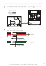
Connect the PV inverter conductors (L1, L2, Neutral, and Ground) to the corresponding
terminals as shown in the figure.
Fasten the PV CT to the PV L1 cable using a cable tie or other method.
Arrange the power cables between the plastic case and metal enclosure and fasten them at
the point indicated by the arrow using a cable tie.
From the PV Inverter
L1 (Black)
L2 (Red)
N (White)
G (Green)
Flat head screwdriver
Depending on wire size.
Follow the guide from
the Eaton BR series.
Flat head screwdriver
2 – 2/0 AWG –
58 kgf·cm (50 lbf·in) torque
6 – 4 AWG –
52 kgf·cm (45 lbf·in) torque
14-8 AWG –
40 kgf·cm (35 lbf·in) torque
y
Refer to "SE Box Wiring: Current Transformer (CT)" for additional diagrams on configuring
energy metering.
y
Refer to "SE Box Wiring: Current Transformer (CT)" for CT configuration troubleshooting
tips.
INFO


