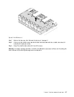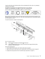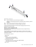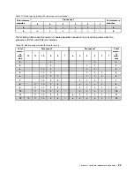
Step 1. Put the backplane under the front I/O assembly cables, align it with the chassis, and lower it into
the chassis. Put the backplane into place with it leaning backward slightly so that the three pins
1
on the chassis pass through the three holes
2
in the backplane.
Step 2. Close the release latches to secure the backplane in place.
After installing the backplane:
1. Connect cables to the backplane. See “Internal cable routing” on page 32.
2. Reinstall all the drives and drive fillers that you removed. See “Install a hot-swap drive” on page 79.
3. Complete the parts replacement. See “Complete the parts replacement” on page 144.
Remove the backplane for eight 2.5-inch hot-swap drives
Use this information to remove the backplane for eight 2.5-inch hot-swap drives.
Ground package before opening”
Before removing the backplane:
1. Remove the top cover. See “Remove the top cover” on page 57.
2. Record the cable connections on the backplane and then disconnect cables from the backplane.
3. Remove all the installed drives and drive fillers (if any) from the drive bays. See “Remove a hot-swap
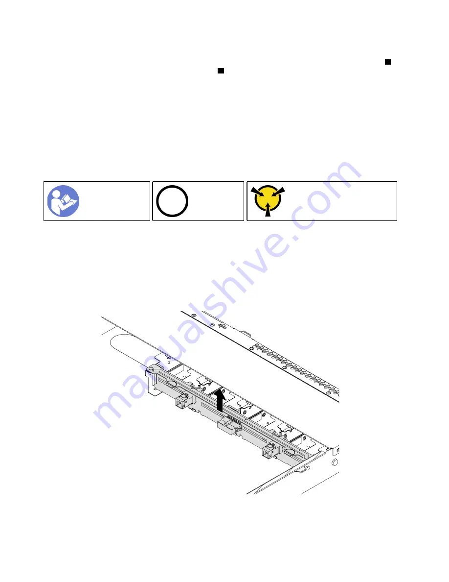
To remove the backplane, complete the following step:
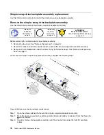
Figure 46. Backplane removal
Step 1. Grasp the backplane and carefully lift it out of the chassis.
74
ThinkSystem SR530 Maintenance Manual
Содержание ThinkSystem SR530
Страница 1: ...ThinkSystem SR530 Maintenance Manual Machine Types 7X07 and 7X08 ...
Страница 8: ...vi ThinkSystem SR530 Maintenance Manual ...
Страница 24: ...16 ThinkSystem SR530 Maintenance Manual ...
Страница 52: ...44 ThinkSystem SR530 Maintenance Manual ...
Страница 72: ...64 ThinkSystem SR530 Maintenance Manual ...
Страница 74: ...66 ThinkSystem SR530 Maintenance Manual ...
Страница 170: ...162 ThinkSystem SR530 Maintenance Manual ...
Страница 174: ...166 ThinkSystem SR530 Maintenance Manual ...
Страница 178: ...170 ThinkSystem SR530 Maintenance Manual ...
Страница 183: ......
Страница 184: ......

