background image

•  YouTube: 

https://www.youtube.com/playlist?list=PLYV5R7hVcs-AQrHuDWK6L3KtHWc6maY_O

•  Youku: 

http://list.youku.com/albumlist/show/id_50437162

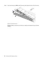
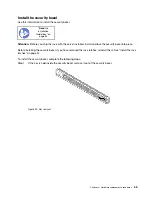
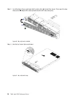
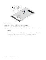
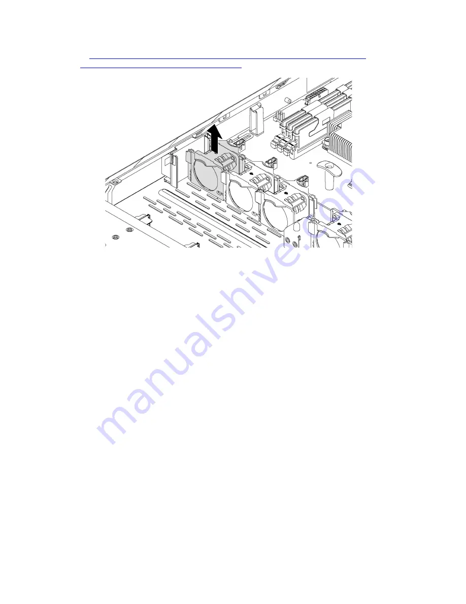
Figure 38. System fan removal

Step 1.  Disconnect the system fan cable from the system board.
Step 2.  Grasp the system fan with your index finger and thumb and carefully lift it straight up. 

After removing the system fan: 

1.  Install a new fan to cover the fan bay.
2.  If you are instructed to return the old system fan, follow all packaging instructions and use any 

packaging materials that are provided.

68

ThinkSystem SR530 Maintenance Manual

Содержание ThinkSystem SR530

Страница 1: ...ThinkSystem SR530 Maintenance Manual Machine Types 7X07 and 7X08 ...

Страница 2: ...dition be sure that you are familiar with the terms and conditions of the Lenovo warranty for your server which can be found at http datacentersupport lenovo com warrantylookup Eleventh Edition June 2021 Copyright Lenovo 2017 2021 LIMITED AND RESTRICTED RIGHTS NOTICE If data or software is delivered pursuant to a General Services Administration GSA contract use reproduction or disclosure is subjec...

Страница 3: ...60 Install the air baffle 62 RAID super capacitor module replacement 63 Remove a RAID super capacitor module 63 Install a RAID super capacitor module 65 System fan replacement 67 Remove a system fan 67 Install a system fan 69 Front I O assembly replacement 70 Remove the front I O assembly 70 Install the front I O assembly 71 Hot swap drive backplane replacement 72 Remove the backplane for four 3 5...

Страница 4: ... number 138 Enable TPM TCM 140 Enable UEFI Secure Boot 143 Complete the parts replacement 144 Chapter 4 Problem determination 145 Event logs 145 General problem determination procedures 147 Resolving suspected power problems 147 Resolving suspected Ethernet controller problems 148 Troubleshooting by symptom 148 Power on and power off problems 149 Memory problems 150 Hard disk drive problems 151 Mo...

Страница 5: ...ligheidsvoorschriften Ennen kuin asennat tämän tuotteen lue turvaohjeet kohdasta Safety Information Avant d installer ce produit lisez les consignes de sécurité Vor der Installation dieses Produkts die Sicherheitshinweise lesen Prima di installare questo prodotto leggere le Informazioni sulla Sicurezza Les sikkerhetsinformasjonen Safety Information før du installerer dette produktet Antes de insta...

Страница 6: ...echnology Lenovo assumes you are qualified in the servicing of equipment and trained in recognizing hazards energy levels in products Access to the equipment is by the use of a tool lock and key or other means of security and is controlled by the authority responsible for the location Important Electrical grounding of the server is required for operator safety and correct system function Proper gr...

Страница 7: ...n 3 Check for any obvious non Lenovo alterations Use good judgment as to the safety of any non Lenovo alterations 4 Check inside the server for any obvious unsafe conditions such as metal filings contamination water or other liquid or signs of fire or smoke damage 5 Check for worn frayed or pinched cables 6 Make sure that the power supply cover fasteners screws or rivets have not been removed or t...

Страница 8: ...vi ThinkSystem SR530 Maintenance Manual ...

Страница 9: ... and tiered system management The server comes with a limited warranty For details about the warranty see https support lenovo com us en solutions ht503310 For details about your specific warranty see http datacentersupport lenovo com warrantylookup Identifying your server When you contact Lenovo for help the machine type and serial number information helps support technicians to identify your ser...

Страница 10: ...vice information Scan the QR code with a mobile device and a QR code reader application to get quick access to the Lenovo Service web site for this server The Lenovo Service Information Web site provides additional information for parts installation and replacement videos and error codes for server support The following illustration shows the QR code https support lenovo com p servers sr530 Figure...

Страница 11: ...us en serverproven index shtml Memory For 1st Generation Intel Xeon Scalable Processor SP Gen 1 Minimum 8 GB Maximum 384 GB using registered DIMMs RDIMMs 768 GB using load reduced DIMMs LRDIMMs Type depending on the model TruDDR4 2666 single rank or dual rank 8 GB 16 GB 32 GB RDIMMs TruDDR4 2666 quad rank 64 GB LRDIMMs Slots 12 slots For 2nd Generation Intel Xeon Scalable Processor SP Gen 2 Minimu...

Страница 12: ...h hot swap SAS SATA drives Up to four 3 5 inch simple swap SATA drives Up to eight 2 5 inch hot swap SAS SATA drives Up to two M 2 drives PCIe slots Depending on the server model your server supports up to three PCIe slots For more information about the PCIe slots see Rear view on page 21 Input Output I O features Front panel One VGA connector One XClarity Controller USB connector One USB 3 0 conn...

Страница 13: ...8i SAS SATA adapter cannot be mixed with RAID 730 8i 1G Cache SAS SATA adapter RAID 730 8i 2G Flash SAS SATA adapter cannot be mixed with RAID 730 8i 1G Cache SAS SATA adapter or RAID 930 8i SAS SATA adapter A RAID super capacitor module must be installed if the RAID 930 8i or 930 16i SAS SATA adapter RAID 930 8e SAS SATA adapter or RAID 730 8i 2G Flash SAS SATA adapter is installed System fans On...

Страница 14: ... and GPUs Electrical input Sine wave input 50 60 Hz required Input voltage low range Minimum 100 V ac Maximum 127 V ac Input voltage high range Minimum 200 V ac Maximum 240 V ac Note For server models with 750 watt ac 80 PLUS Titanium power supplies the 100 127 V ac input voltage is not supported CAUTION 240 V dc input input range 180 300 V dc is supported in Chinese Mainland ONLY Power supply wit...

Страница 15: ...125 m 410 ft of altitude increase Server off 5 45 C 41 113 F Shipping or storage 40 60 C 40 140 F Maximum altitude 3050 m 10 000 ft Relative humidity non condensing Operating ASHRAE class A2 8 80 maximum dew point 21 C 70 F ASHRAE class A3 8 85 maximum dew point 24 C 75 F ASHRAE class A4 8 90 maximum dew point 24 C 75 F Shipping or storage 8 90 Particulate contamination Attention Airborne particul...

Страница 16: ...on or cease functioning altogether This specification sets forth limits for particulates and gases that are intended to avoid such damage The limits must not be viewed or used as definitive limits because numerous other factors such as temperature or moisture content of the air can influence the impact of particulates or environmental corrosives and gaseous contaminant transfer In the absence of s...

Страница 17: ... the rate of copper corrosion growth in the thickness of the corrosion product in Å month and the rate of weight gain assumes that Cu2S and Cu2O grow in equal proportions 3 The derivation of the equivalence between the rate of silver corrosion growth in the thickness of the corrosion product in Å month and the rate of weight gain assumes that Ag2S is the only corrosion product 4 The deliquescent r...

Страница 18: ... following table to determine the best Lenovo tool to use for installing and setting up the firmware Note The server UEFI settings for option ROM must be set to Auto or UEFI to update firmware using Lenovo XClarity Administrator or Lenovo XClarity Essentials For more information see the following Tech Tip https datacentersupport lenovo com us en solutions ht506118 Tool In band update Out of band u...

Страница 19: ...ver updates Notes 1 For I O firmware updates 2 For BMC and UEFI firmware updates The latest firmware can be found at the following site http datacentersupport lenovo com us en products servers thinksystem sr530 7X07 downloads Lenovo XClarity Provisioning Manager From Lenovo XClarity Provisioning Manager you can update the Lenovo XClarity Controller firmware the UEFI firmware and the Lenovo XClarit...

Страница 20: ...tials OneCLI is available at http sysmgt lenovofiles com help topic toolsctr_cli_lenovo onecli_c_update html Lenovo XClarity Essentials UpdateXpress Lenovo XClarity Essentials UpdateXpress provides most of OneCLI update functions through a graphical user interface GUI It can be used to acquire and deploy UpdateXpress System Pack UXSP update packages and individual updates UpdateXpress System Packs...

Страница 21: ...ows operating system and the ibm_rndis_server_os inf file has not been previously installed The file only has to be installed once It is required by Windows operating systems to detect and use the LAN over USB functionality Step 1 Click Administrative Tools Computer Management Device Manager and find the RNDIS Device Click Properties Driver Reinstall driver Point the server to the Windows inf dire...

Страница 22: ...we work toward providing solutions The list of current advisories is available at the following location https datacentersupport lenovo com product_security home Power on the server After the server performs a short self test power status LED flashes quickly when connected to input power it enters a standby state power status LED flashes once per second The server can be turned on power status LED...

Страница 23: ...4 seconds to force a shutdown When in a standby state the server can respond to remote power on requests sent to the Lenovo XClarity Controller For information about powering on the server see Power on the server on page 14 Chapter 1 Introduction 15 ...

Страница 24: ...16 ThinkSystem SR530 Maintenance Manual ...

Страница 25: ...ding on the model your server might look slightly different the illustrations Figure 4 Front view of server models with 3 5 inch drive bays Figure 5 Front view of server models with 2 5 inch drive bays Table 3 Components on the front of the server Callout Callout 1 VGA connector available on some model 2 Pull out information tab 3 XClarity Controller USB connector 4 USB 3 0 connector 5 Operator in...

Страница 26: ...the two functions 4 USB 3 0 connector Attach a USB compatible device such as a USB keyboard USB mouse or USB storage device 5 Operator information panel For information about the controls and status LEDs on the operator information panel see Operator information panel on page 19 6 10 Rack latches If your server is installed in a rack you can use the rack latches to help you slide the server out of...

Страница 27: ...nformation panel Callout Callout 1 Power button with power status 2 Network activity 3 System ID button with ID 4 System error 1 Power button with power status You can press the power button to power on the server when you finish setting up the server You also can hold the power button for several seconds to power off the server if you cannot shut down the server from the operating system The powe...

Страница 28: ...ement program to change the state of the system ID LEDs to assist in visually locating the server among other servers If the XClarity Controller USB connector is set to have both the USB 2 0 function and XClarity Controller management function you can press the ID button for three seconds to switch between the two functions 4 System error LED Status Color Description Action On Yellow An error has ...

Страница 29: ...sembly 2 PCIe slot 2 on riser 1 assembly 3 PCIe slot 3 on riser 2 assembly 4 Power supply 1 5 Power supply 2 available on some models 6 NMI button 7 USB 3 0 connectors 8 VGA connector 9 Ethernet connector 2 RJ 45 10 Ethernet connector 1 RJ 45 11 XClarity Controller network connector 12 Ethernet connector 2 on the LOM adapter available on some models 13 Ethernet connector 1 on the LOM adapter avail...

Страница 30: ...ther devices that use a VGA connector 9 Ethernet connector 2 10 Ethernet connector 1 Used to attach an Ethernet cable for a LAN Each Ethernet connector has two status LEDs to help you identify the Ethernet connectivity and activity For information about the LEDs see Rear view LEDs on page 25 Ethernet connector 1 can be set as XClarity Controller network connector To set Ethernet connector 1 as XCl...

Страница 31: ...ver supports two types of riser cards for riser 1 assembly Type 1 Slot 1 PCIe x16 x8 x4 x1 low profile Slot 2 PCIe x16 x16 x8 x4 x1 full height half length Type 2 Slot 1 PCIe x16 x8 x4 x1 low profile Slot 2 ML2 x8 x8 x4 x1 low profile adapter with full height bracket 3 Power supply 1 4 Power supply 2 available on some models The hot swap redundant power supplies help you avoid significant interrup...

Страница 32: ...troller Network connector start Setup utility go to BMC Settings Network Settings Network Interface Port and select Shared Then go to Shared NIC on and select Onboard Port 1 10 XClarity Controller network connector Used to attach an Ethernet cable to manage the system using XClarity Controller 11 Ethernet connector 2 on the LOM adapter 12 Ethernet connector 1 on the LOM adapter The LOM adapter pro...

Страница 33: ...e server Each time you press the system ID button the state of both the system ID LEDs changes The LEDs can be changed to on blinking or off You can also use the Lenovo XClarity Controller or a remote management program to change the state of the system ID LEDs to assist in visually locating the server among other servers 2 System error LED The system error LED helps you to determine if there are ...

Страница 34: ...he other one delivers the entire load When the power load increases the standby power supply will switch to active state to provide sufficient power to the system To disable zero output mode start the Setup utility go to System Settings Power Zero Output and select Disable If you disable the zero out mode both power supplies will be in the active state Off The server is powered off or the power su...

Страница 35: ...2 Riser 1 slot 3 LOM adapter connector 4 TCM1 TPM2 connector for Chinese Mainland only 5 Front USB connector 6 Front VGA connector 7 DIMM slots 8 Processor 1 socket 9 Operator information panel connector 10 System fan connectors 11 Cable retainer 12 Processor 2 socket 13 Backplane power connector 14 CMOS battery 15 Cable retainer 16 Power supply 2 connector Chapter 2 Server components 27 ...

Страница 36: ...ut 17 Internal USB connector 18 Power supply 1 connector 19 SATA 0 3 connector 20 M 2 module slot 21 Riser 2 slot Notes 1 Trusted Cryptography Module 2 Trusted Platform Module 28 ThinkSystem SR530 Maintenance Manual ...

Страница 37: ...hows the location of the switches and jumpers on the server Note If there is a clear protective sticker on the top of the switch blocks you must remove and discard it to access the switches Figure 11 System board switches and jumpers Chapter 2 Server components 29 ...

Страница 38: ... of this switch does not affect the administrator password 4 Power permission SW6 switch 7 The default position is Off Changing this switch to the On position enables Power On 4 Force XCC reset SW6 switch 4 The default position is Off Changing this switch to the On position resets the Lenovo XClarity Controller 4 Force XCC update SW6 switch 3 The default position is Off Changing this switch to the...

Страница 39: ...odes LEDs on the system board Figure 12 System board LEDs Table 9 LEDs on the system board Callout Callout 1 System error LED 2 System ID LED 3 XClarity Controller heartbeat LED 4 Field Programmable Gate Array FPGA error LED 5 System power LED Chapter 2 Server components 31 ...

Страница 40: ...o the server Cable identifiers of some cables are printed on the cables that come with the server and optional devices Use these identifiers to connect the cables to the correct connectors Ensure that the relevant cables pass through the cable clips Note Disengage all latches release tabs or locks on cable connectors when you disconnect cables from the system board Failing to release them before r...

Страница 41: ... for the video graphic adapter VGA connector Note The VGA connector is available on some models Server models with 3 5 inch drive bays Figure 13 VGA connector cable routing From To 1 VGA cable Front VGA connector on the system board Chapter 2 Server components 33 ...

Страница 42: ...Server models with 2 5 inch drive bays Figure 14 VGA connector cable routing From To 1 VGA cable Front VGA connector on the system board 34 ThinkSystem SR530 Maintenance Manual ...

Страница 43: ...g for the front I O assembly Figure 15 Cable routing for the front I O assembly From To 1 Front USB cable Front USB connector on the system board 2 Operator information panel cable Operator information panel connector on the system board Chapter 2 Server components 35 ...

Страница 44: ...he second RAID adapter in PCIe slot 2 Scenario 2 the second RAID adapter in PCIe slot 3 1 Cable routing for RAID super capacitor module 1 2 Cable routing for RAID super capacitor module 2 An extension cable is provided for each RAID super capacitor module for connection Figure 16 Connecting the RAID super capacitor module to the RAID adapter 36 ThinkSystem SR530 Maintenance Manual ...

Страница 45: ...ives The following illustration shows the cable routing for the server model with eight 2 5 inch hot swap drives Figure 17 Cable routing for the server model with eight 2 5 inch hot swap drives Cable From To 1 Power cable Power connector on the backplane Backplane power connector on the system board 2 SAS signal cable SAS 0 and SAS 1 connectors on the backplane C0 and C1 connectors on the HBA RAID...

Страница 46: ...ows the cable routing for the server model with four 3 5 inch hot swap drives Figure 18 Cable routing for the server model with four 3 5 inch hot swap drives Cable From To 1 Power cable Power connector on the backplane Backplane power connector on the system board 2 SAS signal cable SAS 0 connector on the backplane C0 connector on the HBA RAID adapter 38 ThinkSystem SR530 Maintenance Manual ...

Страница 47: ... 19 Cable routing for the server model with four 3 5 inch simple swap drives The simple swap drive backplate assembly comes with a power cable and a SATA signal cable From To 1 Power cable of the backplate assembly Backplane power connector on the system board 2 SATA signal cable of the backplate assembly SATA 0 3 connector on the system board Chapter 2 Server components 39 ...

Страница 48: ...to http datacentersupport lenovo com us en products servers thinksystem sr530 7x07 parts Note Depending on the model your server might look slightly different from the following illustration Some of the components might not be available on your server Figure 20 Server components The parts listed in the following table are identified as one of the following 40 ThinkSystem SR530 Maintenance Manual ...

Страница 49: ...ervice Table 10 Parts list In dex Description Tier 1 CRU Tier 2 CRU FRU Consuma ble and Structural parts For more information about ordering the parts shown in Figure 20 Server components on page 40 go to http datacentersupport lenovo com us en products servers thinksystem sr530 7x07 parts 1 Top cover 2 Air baffle 3 LOM adapter 4 Riser 1 bracket two low profile 5 Riser 2 bracket one low profile 6 ...

Страница 50: ...nch hot swap drive 27 3 5 inch drive filler 28 3 5 inch simple swap drive 29 3 5 inch hot swap drive 30 CMOS battery CR2032 31 Backplane for eight hot swap 2 5 inch drives 32 Simple swap drive backplate assembly 33 Backplane for four hot swap 3 5 inch drives 34 TCM TPM adapter for Chinese Mainland only 35 DIMM 36 Processor 37 Processor heat sink 42 ThinkSystem SR530 Maintenance Manual ...

Страница 51: ... Standards Association CSA For units intended to be operated at 115 volts Use a UL listed and CSA certified cord set consisting of a minimum 18 AWG Type SVT or SJT three conductor cord a maximum of 15 feet in length and a parallel blade grounding type attachment plug rated 15 amperes 125 volts For units intended to be operated at 230 volts U S use Use a UL listed and CSA certified cord set consist...

Страница 52: ...44 ThinkSystem SR530 Maintenance Manual ...

Страница 53: ...e sure the components you are installing are supported by the server For a list of supported optional components for the server see https static lenovo com us en serverproven index shtml When you install a new server download and apply the latest firmware This will help ensure that any known issues are addressed and that your server is ready to work with optimal performance Go to ThinkSystem SR530...

Страница 54: ...ap drive for any additional procedures that you might need to perform before you remove or install the drive After finishing working on the server make sure you reinstall all safety shields guards labels and ground wires Safety inspection checklist Use the information in this section to identify potentially unsafe conditions with your server As each machine was designed and built required safety i...

Страница 55: ...ou turn the power on Do not operate the server for more than 30 minutes with the server cover removed for it might damage server components Cabling instructions that come with optional components must be followed A failed fan must be replaced within 48 hours since malfunction A removed hot swap fan must be replaced within 30 seconds after removal A removed hot swap drive must be replaced within tw...

Страница 56: ...rostatic discharge wrist strap or other grounding system Limit your movement to prevent building up static electricity around you Take additional care when handling devices during cold weather for heating would reduce indoor humidity and increase static electricity Always use an electrostatic discharge wrist strap or other grounding system particularly when working inside the server with the power...

Страница 57: ...it See Remove the security bezel on page 53 2 Use a flat blade screwdriver to remove the ID label plate on the right rack latch and place it in a safe place Figure 21 ID label plate removal To remove the rack latches complete the following steps Watch the procedure A video of the removal process is available YouTube https www youtube com playlist list PLYV5R7hVcs AQrHuDWK6L3KtHWc6maY_O Youku http ...

Страница 58: ...h screws removal Step 2 On each side of the server remove the rack latch from the chassis as shown Figure 23 Rack latch removal If you are instructed to return the old rack latches follow all packaging instructions and use any packaging materials that are provided 50 ThinkSystem SR530 Maintenance Manual ...

Страница 59: ... installation process is available YouTube https www youtube com playlist list PLYV5R7hVcs AQrHuDWK6L3KtHWc6maY_O Youku http list youku com albumlist show id_50437162 Step 1 On each side of the server align the rack latch with the pin on the chassis then press the rack latch onto the chassis and slightly slide it forward as shown Figure 24 Rack latch installation Chapter 3 Hardware replacement pro...

Страница 60: ...e 25 Rack latch screws installation After installing the rack latches 1 Install the ID label plate to the right rack latch as shown Figure 26 ID label plate installation 2 Complete the parts replacement See Complete the parts replacement on page 144 52 ThinkSystem SR530 Maintenance Manual ...

Страница 61: ... the security bezel Use this information to remove the security bezel Read the installation Guidelines on page 45 To remove the security bezel complete the following steps Step 1 Use the key to unlock the security bezel Figure 27 Security bezel unlock Chapter 3 Hardware replacement procedures 53 ...

Страница 62: ...ivot the security bezel outward to remove it from the chassis Figure 28 Security bezel removal Attention Before you ship the rack with the server installed reinstall and lock the security bezel into place 54 ThinkSystem SR530 Maintenance Manual ...

Страница 63: ...stall and lock the security bezel into place Before installing the security bezel if you have removed the rack latches reinstall them See Install the rack latches on page 51 To install the security bezel complete the following steps Step 1 If the key is held inside the security bezel remove it out of the security bezel Figure 29 Key removal Chapter 3 Hardware replacement procedures 55 ...

Страница 64: ...ide of the chassis Then press the blue release latch 1 and pivot the security bezel inward until it clicks into place Figure 30 Security bezel installation Step 3 Use the key to lock the security bezel Figure 31 Security bezel lockup 56 ThinkSystem SR530 Maintenance Manual ...

Страница 65: ...s energy might cause heating when shorted with metal which might result in spattered metal burns or both S014 CAUTION Hazardous voltage current and energy levels might be present Only a qualified service technician is authorized to remove the covers where the label is attached To remove the top cover complete the following steps Watch the procedure A video of the removal process is available YouTu...

Страница 66: ...ide the cover to the rear until it is disengaged from the chassis Then lift the cover off the chassis and place it on a flat clean surface Attention Handle the top cover carefully Dropping the top cover with the cover latch open might damage the cover latch For proper cooling and airflow install the top cover before you power on the server 58 ThinkSystem SR530 Maintenance Manual ...

Страница 67: ...is free of charge To install the top cover complete the following steps Watch the procedure A video of the installation process is available YouTube https www youtube com playlist list PLYV5R7hVcs AQrHuDWK6L3KtHWc6maY_O Youku http list youku com albumlist show id_50437162 Figure 33 Top cover installation Note Before you slide the top cover forward ensure that all the tabs on the top cover engage t...

Страница 68: ...ns or both S017 CAUTION Hazardous moving fan blades nearby Keep fingers and other body parts away Remove the air baffle Use this information to remove the air baffle Read the installation Guidelines on page 45 Power off the server for this task on page 14 To remove the air baffle complete the following steps Watch the procedure A video of the removal process is available YouTube https www youtube ...

Страница 69: ...ed underneath the air baffle disconnect its cable from the extension cable Step 3 Grasp the air baffle and carefully lift it out of the server Attention For proper cooling and airflow install the air baffle before you power on the server Operating the server without an air baffle might damage server components Chapter 3 Hardware replacement procedures 61 ...

Страница 70: ...ailable YouTube https www youtube com playlist list PLYV5R7hVcs AQrHuDWK6L3KtHWc6maY_O Youku http list youku com albumlist show id_50437162 Figure 35 Air baffle installation Step 1 Align the tabs on both sides of the air baffle with the corresponding slots on both sides of the chassis Step 2 Lower the air baffle into the server and press the air baffle down until it is securely seated After instal...

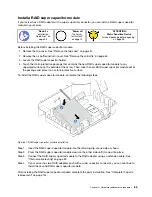
Страница 71: ...ID super capacitor module 1 Remove the top cover See Remove the top cover on page 57 2 Locate the RAID super capacitor module and disconnect its cable The RAID super capacitor holders are located underneath the air baffle 3 Remove the air baffle and turn it over See Remove the air baffle on page 60 To remove the RAID super capacitor module complete the following steps Figure 36 RAID super capacito...

Страница 72: ...64 ThinkSystem SR530 Maintenance Manual ...

Страница 73: ...de of the server Then take the new RAID super capacitor module out of the package and place it on a static protective surface To install the RAID super capacitor module complete the following steps Figure 37 RAID super capacitor module installation Step 1 Insert the RAID super capacitor module into the retaining clip at one side as shown Step 2 Press the RAID super capacitor module down on the oth...

Страница 74: ...66 ThinkSystem SR530 Maintenance Manual ...

Страница 75: ...he device also might have more than one power cord To remove all electrical current from the device ensure that all power cords are disconnected from the power source Remove a system fan Use this information to remove a system fan Read the installation Guidelines on page 45 Power off the server for this task on page 14 ATTENTION Static Sensitive Device Ground package before opening on page 48 Befo...

Страница 76: ...e system fan cable from the system board Step 2 Grasp the system fan with your index finger and thumb and carefully lift it straight up After removing the system fan 1 Install a new fan to cover the fan bay 2 If you are instructed to return the old system fan follow all packaging instructions and use any packaging materials that are provided 68 ThinkSystem SR530 Maintenance Manual ...

Страница 77: ... the following steps Watch the procedure A video of the installation process is available YouTube https www youtube com playlist list PLYV5R7hVcs AQrHuDWK6L3KtHWc6maY_O Youku http list youku com albumlist show id_50437162 Figure 39 System fan installation Step 1 Align the support holes of the system fan with the two pins in the chassis and press it straight down until it is seated into place Note ...

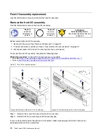
Страница 78: ...ables of the front I O assembly from the system board To remove the front I O assembly complete the following steps Watch the procedure A video of the removal process is available YouTube https www youtube com playlist list PLYV5R7hVcs AQrHuDWK6L3KtHWc6maY_O Youku http list youku com albumlist show id_50437162 Table 11 Front I O assembly removal Figure 40 Server models with 2 5 inch drive bays Fig...

Страница 79: ...ete the following steps Watch the procedure A video of the installation process is available YouTube https www youtube com playlist list PLYV5R7hVcs AQrHuDWK6L3KtHWc6maY_O Youku http list youku com albumlist show id_50437162 Table 12 Front I O assembly installation Figure 42 Server models with 2 5 inch drive bays Figure 43 Server models with 3 5 inch drive bays Step 1 Insert the front I O assembly...

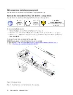
Страница 80: ...emove the top cover See Remove the top cover on page 57 2 Record the cable connections on the backplane and then disconnect cables from the backplane 3 Remove all the installed drives and drive fillers if any from the drive bays See Remove a hot swap drive on page 78 To remove the backplane complete the following steps Watch the procedure A video of the removal process is available YouTube https w...

Страница 81: ...ge 45 Power off the server for this task on page 14 ATTENTION Static Sensitive Device Ground package before opening on page 48 Before installing the backplane touch the static protective package that contains the new backplane to any unpainted surface on the outside of the server Then take the new backplane out of the package and place it on a static protective surface To install the backplane com...

Страница 82: ...ent on page 144 Remove the backplane for eight 2 5 inch hot swap drives Use this information to remove the backplane for eight 2 5 inch hot swap drives Read the installation Guidelines on page 45 Power off the server for this task on page 14 ATTENTION Static Sensitive Device Ground package before opening on page 48 Before removing the backplane 1 Remove the top cover See Remove the top cover on pa...

Страница 83: ...inted surface on the outside of the server Then take the new backplane out of the package and place it on a static protective surface To install the backplane complete the following steps Figure 47 Backplane installation Step 1 Align pins 1 on the backplane with the holes 2 in the chassis Step 2 Lower the backplane into the chassis Ensure that the pins pass through the holes and the backplane is f...

Страница 84: ...er on page 57 2 Record the cable connections and disconnect cables of the simple swap drive backplate assembly 3 Remove all the installed drives and drive fillers if any from the drive bays See Remove a simple swap drive on page 81 To remove the simple swap drive backplate assembly complete the following steps Figure 48 Simple swap drive backplate assembly removal Step 1 Open the release latches t...

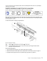
Страница 85: ...e that contains the new backplate assembly to any unpainted surface on the outside of the server Then take the new backplate assembly out of the package and place it on a static protective surface To install the simple swap drive backplate assembly complete the following steps Figure 49 Simple swap drive backplate assembly installation Step 1 Put the backplate assembly under the front I O assembly...

Страница 86: ... occupied by drive fillers When installing a drive save the removed drive filler in case that you later remove the drive and need the drive filler to cover the place To avoid damage to the drive connectors ensure that the top cover is in place and fully closed whenever you install or remove a drive Remove a hot swap drive Use this information to remove a hot swap drive Read the installation Guidel...

Страница 87: ...drive Use this information to install a hot swap drive Read the installation Guidelines on page 45 ATTENTION Static Sensitive Device Ground package before opening on page 48 Notes For a list of supported drives see https static lenovo com us en serverproven index shtml The drive bays are numbered to indicate the installation order starting from number 0 Follow the installation order when you insta...

Страница 88: ... PLYV5R7hVcs AQrHuDWK6L3KtHWc6maY_O Youku http list youku com albumlist show id_50437162 Figure 52 Hot swap drive installation Step 1 Ensure that the drive tray handle is in the open position Slide the drive into the drive bay until it snaps into position Step 2 Close the drive tray handle to lock the drive in place Step 3 Check the drive status LED to verify that the drive is operating correctly ...

Страница 89: ... drive and need the drive filler to cover the place To avoid damage to the drive connectors ensure that the top cover is in place and fully closed whenever you install or remove a drive Remove a simple swap drive Use this information to remove a simple swap drive Read the installation Guidelines on page 45 Power off the server for this task on page 14 ATTENTION Static Sensitive Device Ground packa...

Страница 90: ...the handle and slide the drive out of the drive bay Figure 54 Sliding the drive out of the drive bay Step 3 Install a drive filler or a new drive to cover the drive bay If you are instructed to return the old drive follow all packaging instructions and use any packaging materials that are provided 82 ThinkSystem SR530 Maintenance Manual ...

Страница 91: ...rent capacities in one system but not in one RAID array The following order is recommended when installing the drives Drive type priority SATA SSD SATA HDD Drive capacity priority the lowest capacity first The drives in a single RAID array must be the same type same size and same capacity Before installing a simple swap drive 1 If there is a drive filler installed remove it and keep it in a safe p...

Страница 92: ...ords for this task Memory modules are sensitive to static discharge and require special handling In addition to the standard guidelines for Handling static sensitive devices on page 48 Always wear an electrostatic discharge strap when removing or installing memory modules Electrostatic discharge gloves can also be used Never hold two or more memory modules together so that they touch Do not stack ...

Страница 93: ...vided Memory module installation rules Memory modules must be installed in a specific order based on the memory configuration that you implement on your server Your server supports up to 6 memory modules when one processor is installed and up to 12 memory modules when two processors are installed It supports the following types of memory modules depending on the processors installed For Intel Xeon...

Страница 94: ...ots on the system board Figure 57 Memory module slots on the system board The following memory configurations are available Independent mode on page 86 Mirroring mode on page 87 Rank sparing mode on page 88 Independent mode Independent mode provides high performance memory capability You can populate all channels with no matching requirements Individual channels can run at different memory module ...

Страница 95: ...mbers install the three memory modules in slots 7 8 and 9 Table 14 Independent mode with two processors Total memory modules Processor 2 Processor 1 Total memo ry mod ules 12 11 10 9 8 7 6 5 4 3 2 1 2 9 3 2 3 9 4 3 3 4 10 9 4 3 4 5 10 9 4 3 2 5 6 10 9 8 4 3 2 6 7 10 9 8 5 4 3 2 7 8 11 10 9 8 5 4 3 2 8 9 11 10 9 8 5 4 3 2 1 9 10 11 10 9 8 7 5 4 3 2 1 10 11 11 10 9 8 7 6 5 4 3 2 1 11 12 12 11 10 9 8...

Страница 96: ...11 10 9 8 7 6 5 4 3 2 1 4 9 8 3 2 4 5 9 8 3 2 1 5 6 9 8 7 3 2 1 6 8 11 10 9 8 5 4 3 2 8 9 9 8 7 6 5 4 3 2 1 9 10 11 10 9 8 6 5 4 3 2 1 10 12 12 11 10 9 8 7 6 5 4 3 2 1 12 Rank sparing mode In rank sparing mode one rank of a memory module works as the spare rank for the other ranks on the same channel The spare rank is not available as system memory Notes All memory modules to be installed must be ...

Страница 97: ... processors CPU1 and CPU2 are installed Table 18 Rank sparing mode with two processors Total memo ry mod ules Processor 2 Processor 1 Total memo ry mod ules 12 11 10 9 8 7 6 5 4 3 2 1 2 9 3 2 3 9 4 3 3 4 10 9 4 3 4 5 10 9 4 3 2 5 6 10 9 8 4 3 2 6 7 10 9 8 5 4 3 2 7 8 11 10 9 8 5 4 3 2 8 9 11 10 9 8 5 4 3 2 1 9 10 11 10 9 8 7 5 4 3 2 1 10 11 11 10 9 8 7 6 5 4 3 2 1 11 12 12 11 10 9 8 7 6 5 4 3 2 1 ...

Страница 98: ...ory modules with care never bend twist or drop a memory module Do not use any metal tools such as jigs or clamps to handle the memory modules because the rigid metals may damage the memory modules Do not insert memory modules while holding packages or passive components which can cause package cracks or detachment of passive components by the high insertion force Before installing a memory module ...

Страница 99: ... with both hands Step 3 Firmly press both ends of the memory module straight down into the slot until the retaining clips snap into the locked position Note If there is a gap between the memory module and the retaining clips the memory module has not been correctly inserted In this case open the retaining clips remove the memory module and then reinsert it After installing a memory module complete...

Страница 100: ...umulators that contain heavy metals must not be disposed of with normal domestic waste They will be taken back free of charge by the manufacturer distributor or representative to be recycled or disposed of in a proper manner To order replacement batteries call 1 800 IBM SERV within the U S and 1 800 465 7999 or 1 800 465 6666 within Canada Outside the U S and Canada call your support center or bus...

Страница 101: ..._O Youku http list youku com albumlist show id_50437162 Step 1 Remove the top cover See Remove the top cover on page 57 Step 2 Locate the CMOS battery see System board components on page 27 Step 3 Press the battery clip as shown and carefully lift CMOS battery out of the socket Attention Do not tilt or push the CMOS battery using excessive force Failing to remove the CMOS battery properly might da...

Страница 102: ... disposed of with normal domestic waste They will be taken back free of charge by the manufacturer distributor or representative to be recycled or disposed of in a proper manner To order replacement batteries call 1 800 IBM SERV within the U S and 1 800 465 7999 or 1 800 465 6666 within Canada Outside the U S and Canada call your support center or business partner Note After you install the CMOS b...

Страница 103: ...battery is seated in place Attention Do not tilt or push the CMOS battery using excessive force Any damage to the socket might require replacing the system board Figure 60 CMOS battery installation After installing the CMOS battery 1 Complete the parts installation See Complete the parts replacement on page 144 2 Use the Setup utility to set the date time and any passwords TCM TPM adapter replacem...

Страница 104: ...dapter follow all packaging instructions and use any packaging materials that are provided Install the TCM TPM adapter for Chinese Mainland only Use this information to install the TCM TPM adapter Read the installation Guidelines on page 45 Power off the server for this task on page 14 ATTENTION Static Sensitive Device Ground package before opening on page 48 Before installing the TCM TPM adapter ...

Страница 105: ...M TPM connector on the system board Notes Carefully handle the TCM TPM adapter by its edges Your TCM TPM adapter might look slightly different from the illustration Figure 62 TCM TPM adapter installation After installing the TCM TPM adapter complete the parts replacement See Complete the parts replacement on page 144 Chapter 3 Hardware replacement procedures 97 ...

Страница 106: ...azardous voltage current and energy levels are present inside any component that has this label attached There are no serviceable parts inside these components If you suspect a problem with one of these parts contact a service technician S002 CAUTION The power control button on the device and the power switch on the power supply do not turn off the electrical current supplied to the device The dev...

Страница 107: ...be the information that you must consider when you remove a power supply with dc input CAUTION 240 V dc input input range 180 300 V dc is supported in Chinese Mainland ONLY Power supply with 240 V dc input cannot support hot plugging power cord function Before removing the power supply with dc input please turn off server or disconnect dc power sources at the breaker panel or by turning off the po...

Страница 108: ...e device does not turn off the electrical current supplied to the device The device also might have more than one connection to dc power To remove all electrical current from the device ensure that all connections to dc power are disconnected at the dc power input terminals To remove a hot swap power supply complete the following steps Watch the procedure A video of the removal process is availabl...

Страница 109: ...CMA out of the way to gain access to the power supply Step 2 Disconnect the power cord from the hot swap power supply Note If you are replacing two power supplies do the power supply replacement one by one to ensure that the power supply to the server is not interrupted Do not disconnect the power cord from the secondly replaced power supply until the power output LED for the firstly replaced powe...

Страница 110: ...5 Hot swap power supply removal After removing the power supply Install a power supply filler or a new power supply to cover the power supply bay Important To ensure proper cooling during normal server operation both of the power supply bays must be occupied This means that each bay must have a power supply installed or one has a power supply installed and the other has a power supply filler insta...

Страница 111: ...d For a list of supported optional devices for the server go to https static lenovo com us en serverproven index shtml Notes Ensure that the two power supplies installed on the server have the same wattage If you are replacing the existing power supply with a new power supply of different wattage attach the power rating label that comes with this option onto the existing label on the top cover nea...

Страница 112: ...urce The following tips describe the information that you must consider when you install a power supply with dc input CAUTION 240 V dc input input range 180 300 V dc is supported in Chinese Mainland ONLY Power supply with 240 V dc input cannot support hot plugging power cord function Before removing the power supply with dc input please turn off server or disconnect dc power sources at the breaker...

Страница 113: ...ction to dc power To remove all electrical current from the device ensure that all connections to dc power are disconnected at the dc power input terminals To install a hot swap power supply complete the following steps Watch the procedure A video of the installation process is available YouTube https www youtube com playlist list PLYV5R7hVcs AQrHuDWK6L3KtHWc6maY_O Youku http list youku com albuml...

Страница 114: ...oolless Slide Rail Kit with 1U CMA do the following Figure 67 CMA adjustment a Press down the stop bracket 1 and rotate it to the open position b Rotate the CMA out of the way to gain access to the power supply bay Step 3 If there is a power supply filler installed remove it Figure 68 Hot swap power supply filler removal 106 ThinkSystem SR530 Maintenance Manual ...

Страница 115: ... supply 1 Connect the power cord to the new power supply and ensure that it is connected to a properly grounded electrical outlet 2 If the server is powered off power on the server Ensure that both the power input LED and the power output LED on the power supply are lit indicating that the power supply is operating properly Chapter 3 Hardware replacement procedures 107 ...

Страница 116: ...page 45 Power off the server for this task on page 14 ATTENTION Static Sensitive Device Ground package before opening on page 48 Before removing a PCIe adapter 1 Remove the top cover See Remove the top cover on page 57 2 Remove the riser assembly See Remove a riser card on page 110 To remove a PCIe adapter complete the following steps Table 19 PCIe adapter removal Figure 70 Riser 1 assembly LP LP ...

Страница 117: ...out of the package and place it on a static protective surface To install a PCIe adapter complete the following steps Table 20 PCIe adapter installation Figure 73 Riser 1 assembly LP LP Figure 74 Riser 1 assembly LP FHHL Figure 75 Riser 2 assembly LP Step 1 Align the PCIe adapter with the PCIe slot on the riser card Then carefully press the PCIe adapter straight into the slot until it is securely ...

Страница 118: ...ed on the riser assembly in configuration 2 Remove a riser card Use this information to remove a riser card Read the installation Guidelines on page 45 Power off the server for this task on page 14 ATTENTION Static Sensitive Device Ground package before opening on page 48 To remove a riser card complete the following steps Watch the procedure A video of the removal process is available YouTube htt...

Страница 119: ...tely remove the riser assembly out of the chassis Step 4 Remove the PCIe adapter that is installed on the riser card See Remove a PCIe adapter on page 108 Step 5 Remove the two screws that secure the riser card to the bracket Then remove the riser card Figure 77 Riser card removal If you are instructed to return the old riser card follow all packaging instructions and use any packaging materials t...

Страница 120: ... installation method is the same Step 1 Touch the static protective package that contains the new riser card to any unpainted surface on the outside of the server Then take the new riser card out of the package and place it on a static protective surface Step 2 Note the notch 1 on the riser card and ensure that the orientation of the riser card is correct as shown Then align the screw holes in the...

Страница 121: ...ser card with the riser slot on the system board Then carefully press the riser assembly straight down into the slot until it is fully seated Figure 79 Riser assembly installation After installing the riser card complete the parts replacement See Complete the parts replacement on page 144 Chapter 3 Hardware replacement procedures 113 ...

Страница 122: ...lane and M 2 drive 1 Remove the top cover See Remove the top cover on page 57 2 For easier operation remove the riser assembly next to the M 2 backplane See Remove a riser card on page 110 To remove the M 2 backplane and M 2 drive complete the following steps Watch the procedure A video of the removal process is available YouTube https www youtube com playlist list PLYV5R7hVcs AQrHuDWK6L3KtHWc6maY...

Страница 123: ...hey will both release outward when you slide the retainer backward c Rotate the M 2 drive away from the M 2 backplane d Pull it away from the connector 2 at an angle of approximately 30 degrees If you are instructed to return the old M 2 backplane or M 2 drive follow all packaging instructions and use any packaging materials that are provided Chapter 3 Hardware replacement procedures 115 ...

Страница 124: ...rocedure A video of the adjustment process is available YouTube https www youtube com playlist list PLYV5R7hVcs AQrHuDWK6L3KtHWc6maY_O Youku http list youku com albumlist show id_50437162 Figure 82 M 2 retainer adjustment Step 1 Press both sides of the retainer 1 Step 2 Move the retainer forward until it is in the large opening of the keyhole Step 3 Take the retainer out of the keyhole Step 4 Inse...

Страница 125: ...r on the M 2 backplane to accommodate the particular size of the M 2 drive you wish to install See Adjust the retainer on the M 2 backplane on page 116 3 Locate the connector on each side of the M 2 backplane Notes Some M 2 backplanes support two identical M 2 drives When two M 2 drives are installed align and support both M 2 drives when sliding the retainer forward to secure the M 2 drives Insta...

Страница 126: ...oth sides Step 2 Rotate the M 2 drive down until the notch 1 catches on the lip of the retainer 2 Step 3 Slide the retainer forward toward the connector to secure the M 2 drive into place Attention When sliding the retainer forward ensure that the two nubs 3 on the retainer enter the small holes 4 on the M 2 backplane Once they enter the holes you will hear a soft click sound 118 ThinkSystem SR530...

Страница 127: ...ne installation After installing the M 2 drive and M 2 backplane 1 Reinstall the riser assembly next to the M 2 backplane See Install a riser card on page 112 2 Complete the parts replacement See Complete the parts replacement on page 144 3 Use the Lenovo XClarity Provisioning Manager to configure the RAID For more information see http sysmgt lenovofiles com help topic LXPM RAID_setup html Chapter...

Страница 128: ...mplete the following steps Note The serial port module might be installed on riser 1 assembly or riser 2 assembly The following steps are based on the scenario that the serial port module is installed on riser 2 assembly The removal procedure is the same for the serial port module installed on riser 1 assembly Step 1 Remove the top cover See Remove the top cover on page 57 Step 2 Disconnect the ca...

Страница 129: ...moving the serial port module 1 Install a new serial port module a filler or a PCIe adapter to cover the place 2 If you are instructed to return the old serial port module follow all packaging instructions and use any packaging materials that are provided Chapter 3 Hardware replacement procedures 121 ...

Страница 130: ...e complete the following steps Note The serial port module can be installed on riser 1 assembly or riser 2 assembly The following steps are based on the scenario that the serial port module is to be installed on riser 2 assembly The installation procedure is the same for the serial port module to be installed on riser 1 assembly Step 1 Locate the riser assembly and remove it from the server Step 2...

Страница 131: ...ble the serial port module do one of the following according to the installed operating system For Linux operating system Open the ipmitool and enter the following command to disable the Serial over LAN SOL feature I lanplus H IP U USERID P PASSW0RD sol deactivate For Microsoft Windows operating system a Open the ipmitool and enter the following command to disable the SOL feature I lanplus H IP U ...

Страница 132: ...pter slot To remove the LOM adapter complete the following steps Watch the procedure A video of the removal process is available YouTube https www youtube com playlist list PLYV5R7hVcs AQrHuDWK6L3KtHWc6maY_O Youku http list youku com albumlist show id_50437162 Figure 90 LOM adapter removal Step 1 Loosen the thumbscrew that secures the LOM adapter Step 2 Push the LOM adapter out of the connector on...

Страница 133: ...o install the LOM adapter complete the following steps Watch the procedure A video of the installation process is available YouTube https www youtube com playlist list PLYV5R7hVcs AQrHuDWK6L3KtHWc6maY_O Youku http list youku com albumlist show id_50437162 Figure 91 LOM adapter installation Step 1 Insert the LOM adapter into the rear of the chassis at an angle as shown Step 2 Lower the LOM adapter ...

Страница 134: ...rocessors are supported on the system board with part number 01PE840 If you use the system board with part number 00MX681 update your system firmware to the latest level before installing a Intel Xeon SP Gen 2 processor Otherwise the system cannot be powered on Each processor socket must always contain a cover or a PHM When removing or installing a PHM protect empty processor sockets with a cover ...

Страница 135: ...PHM from the system board Figure 92 Removing a PHM Attention To prevent damage to components make sure that you follow the indicated loosening sequence a Fully loosen the Torx T30 captive fasteners on the processor heat sink module in the removal sequence shown on the heat sink label b Lift the processor heat sink module from the processor socket After you remove a PHM If you are removing the PHM ...

Страница 136: ...hermal grease side down and the processor contact side up to prevent the processor from falling out of the retainer Note The processor retainer will be removed and discarded in a later step and replaced with a new one If you are replacing the processor you will be reusing the heat sink Wipe the thermal grease from the bottom of the heat sink using an alcohol cleaning pad If you are replacing the h...

Страница 137: ...the thermal grease rendering it ineffective Thermal grease can damage components such as electrical connectors in the processor socket Do not remove the grease cover from a heat sink until you are instructed to do so To ensure the best performance check the manufacturing date on the new heat sink and make sure it does not exceed 2 years Otherwise wipe off the existing thermal grease and apply the ...

Страница 138: ...ent than those shown in the illustrations 1 Remove the existing PHM if one is installed See Remove a processor and heat sink on page 126 Note Replacement processors come with both rectangular and square processor retainers A rectangular retainer comes attached to the processor The square retainer can be discarded 2 If you are replacing a heat sink replace the processor retainer Processor retainers...

Страница 139: ...processor using an alcohol cleaning pad Note If you are applying new thermal grease on the top of the processor make sure to do it after the alcohol has fully evaporated 3 If you are replacing a processor a Remove the processor identification label from the heat sink and replace it with the new label that comes with the replacement processor b To ensure the best performance check the manufacturing...

Страница 140: ...e shipping tray If you are replacing a heat sink remove the heat sink from its shipping tray and place the processor and retainer in the opposite half of the heat sink shipping tray with the processor contact side down To prevent the processor from falling out of the retainer hold the processor retainer assembly by its sides with the processor contact side up until you turn it over to fit in the s...

Страница 141: ...with the PHM then insert the PHM into the processor socket Attention To prevent damage to components make sure that you follow the indicated tightening sequence b Fully tighten the Torx T30 captive fasteners in the installation sequence shown on the heat sink label Tighten the screws until they stop then visually inspect to make sure that there is no gap between the screw shoulder beneath the heat...

Страница 142: ...ON Hot surface nearby Remove the system board Use this information to remove the system board Read the installation Guidelines on page 45 Power off the server for this task on page 14 ATTENTION Static Sensitive Device Ground package before opening on page 48 Before removing the system board 1 Remove the top cover See Remove the top cover on page 57 2 Record where the cables are connected to the sy...

Страница 143: ...om playlist list PLYV5R7hVcs AQrHuDWK6L3KtHWc6maY_O Youku http list youku com albumlist show id_50437162 Figure 99 System board removal Step 1 Remove the screws that secure the system board and put the screws in a safe place Step 2 Grasp the system board by the release pin 1 and the lift handle 2 at the same time and gently slide the system board to the front of the server Then lift and tilt the s...

Страница 144: ...n the new system board and orient it correctly above the CPU socket assembly on the removed system board 2 Gently press down the dust cover legs to the CPU socket assembly pressing on the edges to avoid damage to the socket pins You might hear a click on the dust cover is securely attached 3 Make sure that the dust cover is securely attached to the CPU socket assembly 136 ThinkSystem SR530 Mainten...

Страница 145: ...aylist list PLYV5R7hVcs AQrHuDWK6L3KtHWc6maY_O Youku http list youku com albumlist show id_50437162 To install the system board complete the following steps Step 1 Grasp the system board by the release pin 1 and the lift handle 2 at the same time and tilt the system board at an angle of approximately 20 degrees as shown Step 2 Align the hole 3 on the system board with the corresponding mounting st...

Страница 146: ...e machine type and serial number must be updated There are two methods available to update the machine type and serial number From Lenovo XClarity Provisioning Manager V3 To update the machine type and serial number from Lenovo XClarity Provisioning Manager V3 1 Start the server and press F1 to display the Lenovo XClarity Provisioning Manager V3 interface 2 If the power on Administrator password i...

Страница 147: ...zzzzz where zzzzzzz is the serial number access_method The access method that you select to use from the following methods Online authenticated LAN access type the command bmc username xcc_user_id bmc password xcc_password Where xcc_user_id The BMC IMM XCC account name 1 of 12 accounts The default value is USERID xcc_password The BMC IMM XCC account password 1 of 12 accounts Example commands are a...

Страница 148: ...d you must make sure that the TPM TCM policy is set correctly CAUTION Take special care when setting the TPM TCM policy If it is not set correctly the system board can become unusable Set the TPM TCM policy By default a replacement system board is shipped with the TPM TCM policy set to undefined You must modify this setting to match the setting that was in place for the system board that is being ...

Страница 149: ... override imm userid password ip_address 3 Issue reset command to reset system OneCli exe misc ospower reboot imm userid password ip_address 4 Read back the value to check whether the change has been accepted OneCli exe config show imm TpmTcmPolicy override imm userid password ip_address Notes If the read back value is matched it means the TPM_TCM_POLICY has been set correctly imm TpmTcmPolicy is ...

Страница 150: ...y has been disabled 1 Set the hardware Physical Presence jumper on the system board to assert Physical Presence 2 Enable the Physical Presence Policy using either F1 UEFI Settings or Lenovo XClarity Essentials OneCLI Assert Physical Presence through the Lenovo XClarity Controller Complete the following steps to assert Physical Presence through the Lenovo XClarity Controller 1 Log in to the Lenovo ...

Страница 151: ... Advanced Settings Utility ASU commands To set the TPM version to version 2 0 asu64 set TPMVersion TPMVersion Update to TPM2 0 compliant host ip_address user userid password password override To set the TPM version to version 1 2 asu64 set TPMVersion TPMVersion Update to TPM1 2 compliant host ip_address user userid password password override where userid and password are the credentials used to th...

Страница 152: ... components have been reassembled correctly and that no tools or loose screws are left inside your server 2 Properly route and secure the cables in the server See Internal cable routing on page 32 3 If you have removed the top cover reinstall it See Install the top cover on page 59 4 Reconnect external cables and power cords to the server Attention To avoid component damage connect the power cords...

Страница 153: ... using some other management application begin with the Lenovo XClarity Controller event log Event logs An alert is a message or other indication that signals an event or an impending event Alerts are generated by the Lenovo XClarity Controller or by UEFI in the servers These alerts are stored in the Lenovo XClarity Controller Event Log If the server is managed by the Chassis Management Module 2 o...

Страница 154: ...r supply voltages fan speeds and component status The Lenovo XClarity Controller provides various interfaces to systems management software and to system administrators and users to enable remote management and control of a server The Lenovo XClarity Controller monitors all components of the server and posts events in the Lenovo XClarity Controller event log Figure 101 Lenovo XClarity Controller e...

Страница 155: ...ll system tests suspect a network cabling problem that is external to the server Resolving suspected power problems Power problems can be difficult to solve For example a short circuit can exist anywhere on any of the power distribution buses Usually a short circuit will cause the power subsystem to shut down because of an overcurrent condition Complete the following steps to diagnose and resolve ...

Страница 156: ... transmit receive activity is off make sure that the hub and network are operating and that the correct device drivers are installed Step 5 Check the LAN activity LED on the rear of the server The LAN activity LED is lit when data is active on the Ethernet network If the LAN activity LED is off make sure that the hub and network are operating and that the correct device drivers are installed Step ...

Страница 157: ...on about accessing the management controller user interface see the XClarity Controller product documentation http sysmgt lenovofiles com help topic com lenovo systems management xcc doc dw1lm_c_chapter2_ openingandusing html 5 Check http datacentersupport lenovo com for any tech tips service bulletins related to the embedded hypervisor and the server 6 Make sure that other software works on the s...

Страница 158: ...art the server 2 If the problem remains or if you are using an ACPI aware operating system suspect the system board Memory problems Use this information to resolve issues related to memory Displayed system memory less than installed physical memory on page 150 Multiple rows of DIMMs in a branch identified as failing on page 151 Displayed system memory less than installed physical memory Complete t...

Страница 159: ... 6 Trained technician only Replace the system board Hard disk drive problems Use this information to resolve issues related to the hard disk drives Server cannot recognize a hard drive on page 151 Multiple hard drives fail on page 152 Multiple hard drives are offline on page 152 A replacement hard disk drive does not rebuild on page 152 Green hard disk drive activity LED does not represent actual ...

Страница 160: ...If the adapter fails the test disconnect the backplane signal cable from the adapter and run the tests again If the adapter fails the test replace the adapter Multiple hard drives fail Complete the following steps until the problem is solved View the Lenovo XClarity Controller event log for events related to power supplies or vibration issues and resolve those events Make sure that the device driv...

Страница 161: ...rolling or distorted on page 154 The wrong characters appear on the screen on page 154 Incorrect characters are displayed Complete the following steps 1 Verify that the language and locality settings are correct for the keyboard and operating system 2 If the wrong language is displayed update the server firmware to the latest level See Firmware updates on page 9 Screen is blank 1 If the server is ...

Страница 162: ...t least 305 mm 12 in apart and turn on the monitor Notes a To prevent diskette drive read write errors make sure that the distance between the monitor and any external diskette drive is at least 76 mm 3 in b Non Lenovo monitor cables might cause unpredictable problems 2 Reseat the monitor cable 3 Replace the components listed in step 2 one at a time in the order shown restarting the server each ti...

Страница 163: ...n click System Settings Devices and I O Ports USB Configuration 3 If you are using a USB hub disconnect the USB device from the hub and connect it directly to the server Optional device problems Use this information to solve problems related to optional devices External USB device not recognized on page 155 PCIe adapter is not recognized or is not functioning on page 155 A Lenovo optional device t...

Страница 164: ...s successful If the reboot is successful shut down the solution and reinstall the PCIe card you removed If the reboot failed repeat step 2 to step 5 A Lenovo optional device that was just installed does not work 1 Make sure that The device is supported for the server see https static lenovo com us en serverproven index shtml You followed the installation instructions that came with the device and ...

Страница 165: ...ts a Failing serial device b Serial cable 3 Replace the following components a Failing serial device b Serial cable 4 Trained technician only Replace the system board Intermittent problems Use this information to solve intermittent problems Intermittent external device problems on page 157 Intermittent KVM problems on page 158 Intermittent unexpected reboots on page 158 Intermittent external devic...

Страница 166: ... To check the POST watchdog time restart the server and press F1 to display the Lenovo XClarity Provisioning Manager system setup interface Then click BMC Settings POST Watchdog Timer 2 If the reset occurs after the operating system starts disable any automatic server restart ASR utilities such as the Automatic Server Restart IPMI Application for Windows or any ASR devices that are installed 3 See...

Страница 167: ...start System Setup on page 160 Voltage planar fault is displayed in the event log on page 160 Unusual smell on page 161 Server seems to be running hot on page 161 Cracked parts or cracked chassis on page 161 The server immediately displays the POST Event Viewer when it is turned on Complete the following steps until the problem is solved 1 Correct any errors that are indicated by the light path di...

Страница 168: ...s F1 to start System Setup Configuration changes such as added devices or adapter firmware updates and firmware or application code problems can cause the server to fail POST the power on self test If this occurs the server responds in either of the following ways The server restarts automatically and attempts POST again The server hangs and you must manually restart the server for the server to a...

Страница 169: ...ution Order 2 Move the RAID adapter with operation system installed to the top of the list 3 Select Save 4 Reboot the system and auto boot to operation system Cracked parts or cracked chassis Contact Lenovo Support Software problems Use this information to solve software problems 1 To determine whether the problem is caused by the software make sure that The server has the minimum memory that is n...

Страница 170: ...162 ThinkSystem SR530 Maintenance Manual ...

Страница 171: ...lowing location http thinksystem lenovofiles com help index jsp You can take these steps to try to solve the problem yourself Check all cables to make sure that they are connected Check the power switches to make sure that the system and any optional devices are turned on Check for updated software firmware and operating system device drivers for your Lenovo product The Lenovo Warranty terms and c...

Страница 172: ...a new diagnostic to collect new data Lenovo XClarity Controller You can use the Lenovo XClarity Controller web interface or the CLI to collect service data for the server The file can be saved and sent to Lenovo Support For more information about using the web interface to collect service data see http sysmgt lenovofiles com help topic com lenovo systems management xcc doc NN1ia_c_ servicesandsupp...

Страница 173: ...t to obtain help for your issue You can receive hardware service through a Lenovo Authorized Service Provider To locate a service provider authorized by Lenovo to provide warranty service go to https datacentersupport lenovo com serviceprovider and use filter searching for different countries For Lenovo support telephone numbers see https datacentersupport lenovo com supportphonelist for your regi...

Страница 174: ...166 ThinkSystem SR530 Maintenance Manual ...

Страница 175: ...ncorporated in new editions of the publication Lenovo may make improvements and or changes in the product s and or the program s described in this publication at any time without notice The products described in this document are not intended for use in implantation or other life support applications where malfunction may result in injury or death to persons The information contained in this docum...

Страница 176: ...ly supported drives that are available from Lenovo Maximum memory might require replacement of the standard memory with an optional memory module Each solid state memory cell has an intrinsic finite number of write cycles that the cell can incur Therefore a solid state device has a maximum number of write cycles that it can be subjected to expressed as total bytes written TBW A device that has exc...

Страница 177: ...ference suppression devices that are supplied with the monitor Additional electronic emissions notices are available at http thinksystem lenovofiles com help index jsp Taiwan BSMI RoHS declaration Taiwan import and export contact information Contacts are available for Taiwan import and export information Appendix B Notices 169 ...

Страница 178: ...170 ThinkSystem SR530 Maintenance Manual ...

Страница 179: ... web page 163 D devices static sensitive handling 48 DIMM install 90 E enable TPM 140 Ethernet controller troubleshooting 148 Ethernet controller problems solving 148 event logs 145 F firmware updates 9 front I O assembly installing 71 removing 70 replacing 70 G gaseous contamination 8 general problem determination procedures 147 Getting help 163 guidelines options installation 45 system reliabili...

Страница 180: ...replacing 126 monitor problems 153 mouse problems 154 N network problems 158 notes important 168 notices 167 O observable problems 159 operator information panel 19 optional device problems 155 P particulate contamination 8 parts list 40 parts replacement completing 144 PCIe troubleshooting 155 PCIe adapter installing 109 removing 108 replacing 108 PHM installing 129 removing 126 replacing 126 phy...

Страница 181: ...dapter 95 top cover 57 retainer on M 2 backplane adjustment 116 riser card installing 112 removing 110 replacing 110 S safety iii safety inspection checklist iv 46 Secure Boot 143 security advisories 14 security bezel installing 55 removing 53 replacing 53 serial number 138 serial port module installing 122 removing 120 replacing 120 serial device problems 157 server components 17 server power on ...

Страница 182: ...n and power off problems 149 power problems 158 serial device problems 157 symptoms based troubleshooting 148 USB device problems 154 video 153 Trusted Cryptographic Module 140 Trusted Platform Module 140 U UEFI Secure Boot 143 update firmware 9 updating machine type 138 USB device problems 154 V video problems 153 W Windows driver LAN over USB 13 working inside the server power on 47 174 ThinkSys...

Страница 183: ......

Страница 184: ......

Отзывы: