Chapter 2. Server components
Use the information in this section to learn about each of the components associated with your server.
Front view
The front view of the server varies by the model.
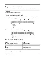
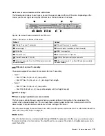
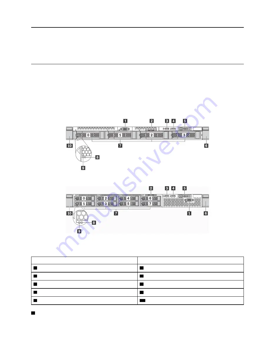
• Front view of server models with 3.5-inch drive bays
• Front view of server models with 2.5-inch drive bays
The following illustrations show the front views of server models with hot-swap drives. Depending on the
model, your server might look slightly different the illustrations.
Figure 4. Front view of server models with 3.5-inch drive bays
Figure 5. Front view of server models with 2.5-inch drive bays
Table 3. Components on the front of the server
Callout
Callout
1
VGA connector (available on some model)
2
Pull-out information tab
3
XClarity Controller USB connector
4
USB 3.0 connector
5
Operator information panel
6
Rack latch (right)
7
Drive bays
8
Drive status LED (yellow)
9
Drive activity LED (green)
10
Rack latch (left)
1
VGA connector (available on some models)
© Copyright Lenovo 2017, 2021
17
Содержание ThinkSystem SR530
Страница 1: ...ThinkSystem SR530 Maintenance Manual Machine Types 7X07 and 7X08 ...
Страница 8: ...vi ThinkSystem SR530 Maintenance Manual ...
Страница 24: ...16 ThinkSystem SR530 Maintenance Manual ...
Страница 52: ...44 ThinkSystem SR530 Maintenance Manual ...
Страница 72: ...64 ThinkSystem SR530 Maintenance Manual ...
Страница 74: ...66 ThinkSystem SR530 Maintenance Manual ...
Страница 170: ...162 ThinkSystem SR530 Maintenance Manual ...
Страница 174: ...166 ThinkSystem SR530 Maintenance Manual ...
Страница 178: ...170 ThinkSystem SR530 Maintenance Manual ...
Страница 183: ......
Страница 184: ......

