


Three-Sources Management System
(T.S.M.S.)
Installa
tion and user manual
19
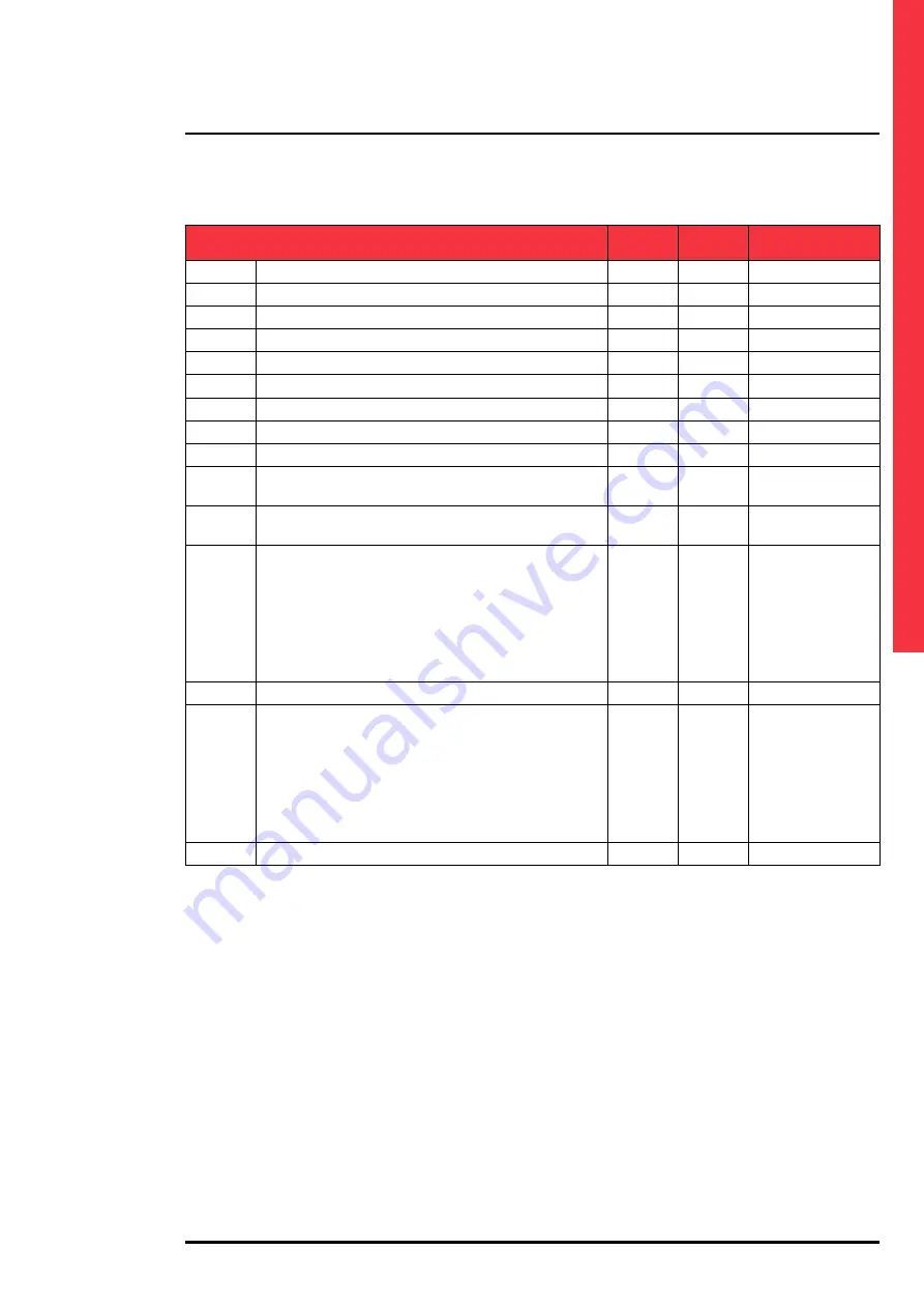
M02 - GENERAL
UNIT
DEFAULT
RANGE
P02.28
Description of tie breaker 1
QC1
(char*4)
P02.29
Description of tie breaker 2
QC2
(char*4)
P02.30
Tie breaker closing delay
sec
5.0
0.1 … 60.0
P02.31
Pre-transfer time load 1
sec
OFF
OFF / 1-1000
P02.32
Post-transfer time load 1
sec
OFF
OFF / 1-1000
P02.33
Pre-transfer time load 2
sec
OFF
OFF / 1-1000
P02.34
Post-transfer time load 2
sec
OFF
OFF / 1-1000
P02.35
Pre-transfer time load 3
sec
OFF
OFF / 1-1000
P02.36
Post-transfer time load 3
sec
OFF
OFF / 1-1000
P02.37
Tie breaker QCC1 continuous control in RESET/OFF mode
NOC
OFF
NOC
P02.38
Tie breaker QCC2 continuous control in RESET/OFF mode
NOC
OFF
NOC
P02.39
Tie breaker QC21 conditional enable
OFF
OFF
INPx
OUTx
LIMx
REMx
PLCx
Ax
UAx
P02.40
Function index (x)
OFF
OFF / 1…99
P02.41
Tie breaker QCC2 conditional enable
OFF
OFF
INPx
OUTx
LIMx
REMx
PLCx
Ax
UAx
P02.42
Function index (x)
OFF
OFF / 1…99
P02.01 - System layout, description of the various configurations with respective logical diagrams is shown in this manual
in the system layout section at the end of the parameter description section:
P02.02 - Rated system voltage. Set the concatenated voltage for polyphase systems.
P02.03 - Use voltage transformers (VT) on the voltage measuring inputs.
P02.04 - Primary value of any voltage transformers.
P02.05 - Secondary value of any voltage transformers.
P02.06 - Phase sequence control enabling. OFF = no control. Direct = L1-L2-L3. Inverted = L3-L2-L1. Note: The corre-
sponding alarms must also be enabled.
P02.07 - Connection type choice, three-phase with/without neutral, two-phase or single-phase.
P02.08 - Voltage controls on concatenated voltages, phase voltages or both.
P02.09 - Rated system frequency.
P02.16 – Defines whether to manage non-priority load management (for system layouts which does not reuire it specifi-
cally). In addition to enabling management, it defines the control type for the breaker which controls it.
P02.17 – Timeout between sending of a control to the non-priority load breaker and the actual execution of the opera-
tion. After having sent an opening or closing control to the breaker, alarm A31 is generated if it is not positioned
correctly within the timeout. It works when the auxiliary state contacts of the breaker is programmed and wired.
P02.18 – Minimum opening control time. For applications with motorised breakers, this must be set to a sufficient time to
allow complete charging of the springs. This time is considered also when working in continuous control mode.
P02.19 – Closing control pulse time.
P02.20 – Minimum coil deactivation pulse for breaker opening pulse.
P02.21 – Time elapsed between minimum voltage opening pulse and breaker spring loading control.