background image


117


3.6 Adjusting the Peel-Detection Rollers


REGIUS MODEL 190 Service Manual Ver.1.00 2004.11.01


3.6

Adjusting the Peel-Detection Rollers


3.6.1


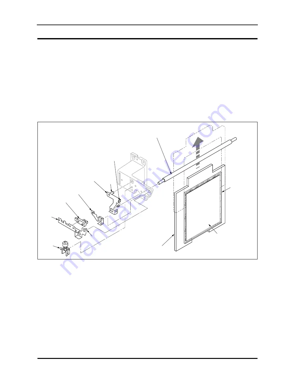
Peel detection mechanism


The REGIUS 190 has been designed such that, when subscanning operation is being carried out, there is a gap 

of approximately 1 mm between the optical beam condensing section and the plate surface. However, in situa-

tions such as where abnormal adherence of double-sided adhesive tape leads to peeling of the plate from the 

back plate, any attempted subscanning operation could result in interference of the plate with the optical unit. In 

order to avoid such interference, a peel detection roller is provided in the position where the elevating plate is just 

enters the operational area of optical unit.


•  


Main Components of Peel Detection Mechanism


Sensor Actuator

Shaft "A"

Shaft "B"

1

4

6

3

5

2

Magnetizing Plate

REGIUS Plate

Back Plate

Содержание REGIUS 190

Страница 1: ...REGIUS MODEL 190 DD 941 SERVICE MANUAL No 26 2 Nishishinjuku 1 chome Shinjuku ku Tokyo 163 0512 Japan DIRECT DIGITIZER CODE NO 0676 2nd EDITION DEC 2004...

Страница 2: ...ocations of Sensors and Switches 15 1 4 Block Diagram 17 1 5 Description of Operation 19 1 5 1 Operation Flow 19 1 5 2 Normal Operation 20 1 5 3 Initializing Sequence 23 1 5 4 Erase Operation 23 1 6 R...

Страница 3: ...iver Sensor 63 2 5 Subscan Unit 64 2 5 1 Controlling Parts of subscan Unit 64 2 5 2 Replacement of Cassette Magnetizing Plate 66 2 5 3 Steel Belt Decelerating Unit 68 2 5 4 Replacement of Peel Detect...

Страница 4: ...ence 105 3 4 Verification of Reading Operation 108 3 5 Checking the Stand Alone Operation 116 3 6 Adjusting the Peel Detection Rollers 117 3 6 1 Peel detection mechanism 117 3 6 2 Adjustment of the St...

Страница 5: ...correction data is excessive i e 300 steps or more from MAX to MIN 145 4 3 15 Case 14 S value variation 146 4 3 16 Case 15 Poor contrast raw data 146 4 3 17 Case 16 Density differs from the left to t...

Страница 6: ...ue 175 A 1 7 Maintenance Window 176 A 1 8 Get Task Information Dialogue 182 A 1 9 Change data Dialogue 182 A 1 10 Firmware Update Parameters Dialogue 183 A 2 DIP Switch Setting 184 A 2 1 DIP Switches...

Страница 7: ...VI REGIUS MODEL 190 Service Manual Ver 1 00 2004 11 01...

Страница 8: ...installing the REGIUS 190 for a field service engineer Be sure to carefully read and understand this manual before installing the REGIUS 190 TRADEMARK Microsoft and Windows are trademarks of Microsoft...

Страница 9: ...onsole just after exposure allows the doctor to check images on the spot 6 Sampling pitch can be selected from 43 75 m 87 5 m and 175 m depending on diagnostic purposes 7 Cassette size can be selected...

Страница 10: ...ins 6 Stand by ON OFF The main power source will still be ON even when this is turned OFF 7 Dangerous voltage 8 Type B applied part 9 High temperature cautions The part indicated with this symbol beco...

Страница 11: ...ury or dam age as explained below DANGER Indicates an acute hazard that will result in death or serious injury if not avoided WARNING Indicates a danger that may result in death or serious injury if n...

Страница 12: ...UTION The basic cautions to be observed when installing or operating the REGIUS MODEL 190 are described in this chapter Be sure to read the descriptions in this chapter and drive the users home to the...

Страница 13: ...Blank...

Страница 14: ...g transportation 4 Do not install the equipment in a location where chemical reagents are stored or where chemical fumes may be present 5 Check the frequency voltage and allowable current or power con...

Страница 15: ...etc Store the equipment in a stable location Do not store it on an inclined surface and avoid vibrational shock including during transportation Do not store the equipment in a location where chemical...

Страница 16: ...ing servicing never peel or soil the labels on the REGIUS MODEL 190 CAUTION If the label gets soiled or falls off and the caution is no Longer legible replace it with a new one Warning Labels Warning...

Страница 17: ...anual Ver 1 00 2004 11 01 Warning for Foreign Object Warning for Laser Do not place anything on the inner shelf Warning for Laser External Be careful of static electricity it may damage the electronic...

Страница 18: ...Warning Labels Exterior Transport Unit Cassette Magne tizing Plate Warning for LCD fall Warning for Ejection Slot Warning for Laser Exterior Warning for Magnetizing Plate Warning for High Temperature...

Страница 19: ...GIUS MODEL 190 Service Manual Ver 1 00 2004 11 01 Front Door inner shelf Steel Belt Optical Unit Do not place anything on the inner shelft Warning for Electrostatic Warning for Steel Belt Warning for...

Страница 20: ...Use Power supply breakers should be switched off following prescribed proce dures When disconnecting be sure to hold cables properly All accessories and cables should be cleaned and set in order at th...

Страница 21: ...onsulted immediately If the coating comes into contact with the skin the affected area should be immediately rinsed with clean water Even if the coating has not been ingested care must be taken to ens...

Страница 22: ...ning properly and check for bending or other damage Do not insert damaged cassettes into the REGIUS MODEL 190 Make sure that there is no paper clipped into the memo clip on the back plate Make sure th...

Страница 23: ...L 190 incorporates high voltage parts which pose the risk of electrocution if touched WARNING To minimize risk only properly trained service personnel are allowed to remove covers or handle internal c...

Страница 24: ...lines Cautions Relating to Lithium Batteries The SCB2 System Control Board in the REGIUS MODEL 190 incorpo rates a lithium battery Unless given specific instructions the lithium battery should not be...

Страница 25: ...osal this product must be handled in accordance with the appropriate waste disposal regulations Disposal of the product must be carried out in accordance with local ordinances and regulations Part tha...

Страница 26: ...ife Expectancy The above figure is valid on condition that the part is used in accordance with prescribed cautions relating to usage and is properly maintained and inspected The above figure should be...

Страница 27: ...xx REGIUS MODEL 190 Service Manual Ver 1 00 2004 11 01...

Страница 28: ...Chap 1 Overview...

Страница 29: ...Blank Page...

Страница 30: ...4892 14 x 14 352 0 x 352 0 2010 x 2010 4020 x 4020 11 x 14 275 0 x 352 0 1570 x 2010 3140 x 4020 10 x 12 250 5 x 301 5 1430 x 1722 2860 x 3444 8 x 10 199 5 x 250 5 1140 x 1430 2280 x 2860 24 x 30cm ma...

Страница 31: ...i e Super High Precision Mode 43 75 m High Precision mode 87 5 and Normal mode 175 Max Reading Size mm 352 0 x 428 5 14 x 17 cassette Max Number of Pixels 7080 x 9480 QR Value 3 types i e Low Sensiti...

Страница 32: ...gon Faces 7 inscribed circle diameter 82 Rotation Speed of Polygon 2 types 1 137rpm 1 648rpm Laser Wavelength 660nm On Plate Laser Inten sity 35mW or higher Imaging beam diameter100 100 or less for bo...

Страница 33: ...ire elimination digital filtering Calculation for gain and offset correction Calculation for correction of irregularity in the main scanning direction shading correction and polygon correction Calcula...

Страница 34: ...10 60Hz AC200 220 230 240V 10 50Hz Environment Temperature Humidity At operation 15 30 C 35 80 RH no condensation At storage 10 40 C 10 95 RH no condensation Noise 60dB or less Regular Spare Parts Era...

Страница 35: ...me of Parts 1 2 1 External View of REGIUS 190 Front Right LCD Panel operation SW erase SW operation Lamp Gr erase Lamp Or READY Lamp Insertion Ejection Front Cover Exit Guide Front Cover Cassette Disc...

Страница 36: ...9 1 2 Name of Parts REGIUS MODEL 190 Service Manual Ver 1 00 2004 11 01 Rear Left Ethernet Port AC Inlet Rear Cover Circuit Breaker Left Cover...

Страница 37: ...d converts the light through condenser tube into the electrical signal Insertion Ejec tion Slot Draws a cassette into the device which the operator inserts Ejects the cassette after reading onto the c...

Страница 38: ...1 2 3 Name of Cassette Parts X X X X X X X X X X X x x x x x Size Indication Label Steel Plate Claw Open Close Lock Bar Code Label Memo Clip Back Plate CE Marking X X X X X X X X X X X x x x x x Front...

Страница 39: ...delivered has following information 1 2 1 2 1 2 3 1 2 3 4 5 6 7 Cassette Size 2 digits 00 14 x17 01 14 x14 02 11 x14 03 10 x12 04 8 x10 05 24x30cm 06 18x24cm 07 24x30cm Mammography 08 18x24cm Mammogra...

Страница 40: ...t Name 1 SUP1 DC5V 24V power supply 8 ADB2 A D board 2 PSB 15V power supply 9 MCB2 Mechanical control board 3 Power Transformer PT1 10 LCD Panel 4 SUP3 Halogen power supply 11 GYB Green Yellow LED boa...

Страница 41: ...8 MCB2 Cooling Fan FM4 2 DC Power Supply Cooling Fan FM2 9 Justification Motor PM2 3 Halogen Cooling Fan FM3 10 Transportation Motor PM3 4 Main Unit Exhaustion Fan FM1 11 Lock Release Motor M4 5 Speak...

Страница 42: ...r Open Sensor S19 18 Lock Release Sensor S1 6 Bar Code Reader 19 Thermostat TM1 7 eject SW SW5 20 Sync Sensor S12 8 Insertion Slot Sensor Emission LLB1 LLB2 21 Absorption Magnetizing Detect Sensor S15...

Страница 43: ...16 1 3 Layout of Controlling Components REGIUS MODEL 190 Service Manual Ver 1 00 2004 11 01...

Страница 44: ...ptor 1 LPB1 Insertion Slot Sensor Emission 2 LLB2 Insertion Slot Sensor Receptor 2 LPB2 Insertion Shutter Open Sensor S18 Insertion Shutter Close Sensor S19 Eject Shutter Close S20 Cassette Back Plate...

Страница 45: ...Blank Page...

Страница 46: ...ation Power OFF READY Status Error Status ERASE MODE 1 Count Down ERASE MODE 2 Count Down Initializing Process Power OFF Process Image Reading Image Erasure Image Erasure High Speed Mode Image Erasure...

Страница 47: ...nds after the insertion slot sensors turn off the shutter closes When the cassette has been fully drawn into the transport section the width justification motor drives the width justifi cation mechani...

Страница 48: ...fter the V SYNC sensor turns on the laser also turns on and image reading operations start 8 When the image reading has been completed the absorp tion plate moves down and simultaneously the erasing l...

Страница 49: ...t of back plate detachment or the like the cas sette passes the ejection shutter without a front plate the back plate sensor does not turn on and an error is gener ated If a subsequent cassette is ins...

Страница 50: ...s the normal opera tion Erasing will be completed in step 7 of 1 5 2 Normal Operation 1 Insertion Slot Shutter Initialization of the insertion slot shutter is implemented 2 Justification Assy Justific...

Страница 51: ...d screwdriver Torque driver Peel detection roller tester Front door interlock release key Maintenance PC Unit checker RS 232C cable Dummy SCB2 Software Maintenance tool software Laser goggle Earth str...

Страница 52: ...Chap 2 Disassembly and Reassembly...

Страница 53: ...Blank Page...

Страница 54: ...nfirm that they have not become trapped between or caught on components Sensors are still electified even after the interlock has been disengated Be careful not to short cir cuit the sensors Except fo...

Страница 55: ...190 Service Manual Ver 1 00 2004 11 01 2 2 Removing the External Covers 2 2 1 Removal of the Rear Cover 1 Unscrew and remove the four fixing screws 4pcs 2 Grip the handle and lift up the rear cover t...

Страница 56: ...Important Sems screws M4 x 12mm are used to retain the right and left covers Be cau tious not to loose them nor to use them for other purpose 1 Unscrew and remove the four fixing screws 2 Slide the c...

Страница 57: ...r 3 Lift the front top cover 2 3mm Then tilt the front top cover towards the front until a gap of approximately 100 mm opens up between that cover and the front cover 4 Uncouple the connector from the...

Страница 58: ...Important Sems screws M4 x 12mm are used to retain the insertion ejection front cover Be cautious not to loose them nor to use them for other purpose 1 Open the front cover 2 Remove two fixing screws...

Страница 59: ...terminal from the front top cover 3 Remove two fixing screws b and remove the display assy 4 Remove two fixing screws a and remove the mount plate 5 Unplug a relay connector JJ15 6 Remove 4 fixing scr...

Страница 60: ...2 Remove the cassette stacker Refer to 2 3 4 Replacement of Bar Code Reader p 40 3 Remove the stay Refer to 2 3 4 Replacement of Bar Code Reader p 40 4 Remove the fixing screws one for each sensor 5...

Страница 61: ...Cover p 31 2 Remove the insertion guide Refer to 2 3 5 Replacement of Insertion Nip Rollers p 41 3 Remove tow fixing screws from the sensor 4 Pull out the fasten terminal COM terminal Black NC termina...

Страница 62: ...Removal of Insertion Ejection Front Cover p 31 2 Remove the sensor bracket 3 Remove the sensor from the sensor bracket 4 Unplug a connector JP53 2 Insertion Shutter Open Sensor S19 Detects the inser...

Страница 63: ...ject sensor wiring Refer to 2 3 8 Replacement of Ejection Motor M3 p 45 3 Remove the eject sensor bracket Refer to 2 3 8 Replacement of Ejection Motor M3 p 45 4 Remove the sensor from the eject sensor...

Страница 64: ...f the Left Right Covers p 29 3 Remove the front top cover 2 2 3 Removal of the Front Top Cover p 30 4 Loosen 6 fixing screws Then detach board cover 5 Loosen the 5 fixing screws and then remove the li...

Страница 65: ...g the position of the Transport Unit at the time it may require to tilt the Transport Unit using a handle so that the hand can reach the part 10 Hold the insertion ejection unit as shown in the right...

Страница 66: ...2 4 Removal of Insertion Ejection Front Cover p 31 2 Remove 4 fixing screws 2 on each side 3 Unplug two relay connectors JJ46 JJ59 4 First slide the ejection guide assy toward rear of the main unit li...

Страница 67: ...Assy p 39 2 Remove three fixing screws and remove the cassette stacker 3 Remove 4 fixing screws a and remove the stay 4 Remove two fixing screws b and remove the bar code reader from the stay 5 Remov...

Страница 68: ...ve the front top cover 2 2 3 Removal of the Front Top Cover p 30 4 Remove the insertion ejection unit 2 3 2 Removal of the Insertion Ejection Unit p 37 5 Remove the insertion ejection unit front cover...

Страница 69: ...emove an E ring and remove shaft bearing B x 1 from the right of the roller shaft 10 Remove the insertion roller front 11 Remove E rings one on each side from the both shaft ends and remove the insert...

Страница 70: ...oval of Insertion Ejection Front Cover p 31 2 Remove three fixing screws and remove the insertion motor M1 3 Detach the wire bundle from the wire clamp and unplug a connector JJ47 4 Remove an E ring a...

Страница 71: ...2 2 4 Removal of Insertion Ejection Front Cover p 31 3 Remove an E ring and then an idler gear At the same time a parallel pin will also become free Be cautious not to loose this pin 4 Remove the wir...

Страница 72: ...1 3 Remove two fixing screws and remove the guide plate for the ejection sensor wiring The fixing screws used here are M3 x 6 2pcs 4 Remove two fixing screws and remove the ejection sensor bracket 5 R...

Страница 73: ...the right and left frame and remove the ejection shutter assy from the insertion ejec tion unit 10 Remove 4 fixing screws and remove the tray assy 11 Remove two fixing screws and remove the tray assy...

Страница 74: ...reassembly in the reverse order to that described above Remarks for Installation Assembling the ejection shutter step9 Confirm that the arm for shutter spring is properly set in the damper gear assy L...

Страница 75: ...the eject sensor bracket is held up Confirm that the sensor pin stays close to the center of the ejection sensor when the ejection shutter closes Ejection sensor wiring guide plate step3 Confirm that...

Страница 76: ...ion Access to the Part 1 Feed Escape Sensor S11 Detects the evacu ation position of the base 1 Remove the right cover Refer to 2 2 2 Removal of the Left Right Covers p 29 2 Remove two fixing screws an...

Страница 77: ...e frame comes in contact 2 Feed HP Sensor S10 Detects the HP of the base 1 Remove the right cover Refer to Removal of the Left Right Covers p 29 2 Remove two fixing screws and remove the transport sen...

Страница 78: ...ification mechanism to the center by hand 3 Remove a fixing screw and remove the justification sensor mount plate 4 Remove the sensor from the justification sensor mount plate 5 Unplug a connector JP2...

Страница 79: ...e front cover and tilt the Transport Unit using handle 2 Remove a fixing screw and remove the sensor 3 Unplug a connector JP31 2 Elevator Motor PM1 Drives the receiver via belt and elevate the receive...

Страница 80: ...elease shaft 1 Remove the receiver assy Refer to 2 4 2 Removal of the Cassette Receive Unit p 54 2 Unplug a connector JP20 3 Remove the sensor from the release sensor bracket 3 Lock Release Motor M4 A...

Страница 81: ...screws painted in white must not be removed and if this precaution is not observed it may become impossible for cassettes to be correctly passed from the Transport Unit to the subscan ning section 4...

Страница 82: ...to tilt the Transport Unit 5 Remove two fixing screws a and detach the cover for jus tification motor 6 Uncouple the connector from the justification motor JP29 7 Remove two fixing screws and remove t...

Страница 83: ...s and remove the pulley cover for justification mechanism 2 The width justification motor is to be secured in such a way that a 2 mm deflection in the center of the belt will be caused by a load of be...

Страница 84: ...ght position the trans portation rack gear is being pressed down by the weight of the Transport Unit rendering it difficult to remove the unit 4 Remove three fixing screws a and remove the rack gear h...

Страница 85: ...e right sector plate with two fixing screws 14 Install the rack gear holder pad on the right sector plate with three fixing screws Lubrication after installation Lubricate the pinion gear on the trans...

Страница 86: ...notch in the elevator motor s cover 5 Remove the elevator motor s cover 6 Remove the two fixing screws b which are securing the elevator motor 7 Unplug the connector from the elevator motor JP28 8 Rem...

Страница 87: ...e the two fixing screws and detach the transport motor cover 3 Unplug the connector from the transport motor JJ2830 4 Remove the two fixing screws and remove the transport motor The coupling green may...

Страница 88: ...and remove the receiver motor bracket 3 Cut the wire bundle of the receiver motor bracket 4 Unplug the connector JJ19 5 Remove the three fixing screws and remove the unlock motor M4 from the receiver...

Страница 89: ...oint and cause a trouble in operation Before fixing the screw for the receiver motor bracket confirm that the top edge of the guide shaft is correctly fitted into the hole of the receiver motor bracke...

Страница 90: ...screws and remove the receiver sensor bracket 4 Unplug the connector from the receiver JP21 5 Remove the receiver sensor S2 from the receiver sensor bracket 6 Carry out reassembly in the reverse order...

Страница 91: ...ing Parts of subscan Unit 1 2 3 4 Magnetic Plate Steel Belt Part Name Function Access to the Part 1 V sync Sensor S12 Detects the read start position of sub scan ning direction 1 Remove the sensor ass...

Страница 92: ...ing plate 1 Remove the sensor assy Refer to 2 5 5 Removal of the Sensor Assembly p 71 2 Unplug the connector JP45 3 Remove a fixing screw and remove the sensor 4 Subscan Motor PM4 Moves the cassette m...

Страница 93: ...anually raise the balance weight up to the top level 3 Remove the two fixing screws and remove the anti fall pro tection metal yellow 4 While holding the bottom of balance weight secure the anti fall...

Страница 94: ...o positioning pins which are located between the fixing screws are properly sit in the hole tighten the fixing screws Attach the anti fall protection metal to its original position from which it was d...

Страница 95: ...top cover 4 Remove the cassette magnetizing plate 2 5 2 Replacement of Cassette Magnetizing Plate p 66 5 Place a paper on the top cover This will help to avoid causing scratches on the steel belt when...

Страница 96: ...12 Carry out reassembly in the reverse order to that described above Important When securing the steel belt to the bal ance weight check that the steel belt is not pinched between the bearing and wash...

Страница 97: ...2 Remove a fixing screw a detach the peel detect sensor L mount plate or peel detect sensor R mount plate 3 Remove a fixing screw b which is securing the peel detect sensor and detach the peel detect...

Страница 98: ...anually raise the balance weight to the top 3 Uncouple the relay connector and push it out to the front through the hole in the main unit JP65 4 Lower the balance weight to the bottom by hand 5 Move t...

Страница 99: ...igure slide the assy up If the slide roller is in upright position it interferes with the activator receptor plate and cannot be slid in When sliding the sensor assy up align the assy to the left end...

Страница 100: ...2 Removal of the Left Right Covers p 29 3 Unplug the connector from the subscanning motor JP35 4 Loosen the set screw on the coupling Loosening the set screw releases the link between the subscan moto...

Страница 101: ...removed ensure that the hole which it was covering remains oriented upward 3 Attach the subscanning motor to the main body using four fixing screws 4 Use a hexagonal screwdriver or the equivalent to e...

Страница 102: ...fixing screws to remove the board cover 3 Unplug two connectors from the analog digital board ADB2 J1 J3 4 Remove four fixing screws and remove the photomultiplier from the optical unit Important Whe...

Страница 103: ...ultiplier 2 6 1 Replacement of Photomultiplier PMT p 75 6 Unplug a relay connector JJ37 7 Remove 5 fixing screws The fixing screw on the upper right also fixes the earth cable of the optical unit to t...

Страница 104: ...004 11 01 Check and adjustment after installation Always carry out the calibration below following the Installation Service Manual for REGIUS Console Confirmation of Shading Correction Sensitivity Cal...

Страница 105: ...do not touch the erase lamp immediately after it is extinguished 1 Remove the right cover See page p 29 2 Unplug two connectors JJ12 JJ13 3 If the dust proof blade is not drawn out the erase lamp uni...

Страница 106: ...Cover p 30 4 Remove the insertion ejection unit 2 3 2 Removal of the Insertion Ejection Unit p 37 5 Remove the photomultiplier 2 6 1 Replacement of Photomultiplier PMT p 75 6 Remove the optical unit 2...

Страница 107: ...rews and detach the board cover 3 Turn OFF set to the right the HVSW SW3 high voltage SW of the ADB2 A D board 4 Connect the oscilloscope to TP10 HSYNC located at the upper left and to TP7 AGND locate...

Страница 108: ...5 fixing screws and remove the MCB2 box cover 3 Put note of the setting of rotary SW SW4 and DIP SW SW3 This setting has been adjusted in 3 7 Adjusting the Pressing Amount p 122 and varies from one ma...

Страница 109: ...out reassembly in the reverse order to that described above Remarks for Installation Set the rotary SW SW4 and DIP SW SW3 on the new board according to the note taken in step 3 Check that the DIP SW S...

Страница 110: ...onsole in advance All related settings necessary when the CF card is replaced refer to 5 3Replacement Procedures of CF Card p 187 CF card is installed in the card slot on the SCB2 1 Detach the left co...

Страница 111: ...the backed up data from the REGIUS Console onto the CF card by following the Installation Service Manual for REGIUS Con sole 1 Detach the left cover 2 2 2 Removal of the Left Right Covers p 29 2 Loos...

Страница 112: ...was changed in setting at the time of installa tion because of different host name IP address subnet set ting In this case set the network first referring to A 3 Replacement Procedures of CF Card p 1...

Страница 113: ...t the SCB2 5 Unplug 8 connectors from ADB2 CN2 CN3 CN4 CN5 CN7 CN8 J1 J3 6 Remove 5 fixing screws and pull out ADB2 7 Carry out reassembly in the reverse order to that described above Remarks for inst...

Страница 114: ...rs from PSB 15V supply JP6 JP7 3 Remove a fixing screw and pull out the PSB from board s support legs 3pcs 4 Carry out reassembly in the reverse order to that described above Remarks for installation...

Страница 115: ...an excessive force 4 Unplug a relay connector of the DC supply cooling fan JJ60 5 Unplug two connectors from SUP1 DC5V 24V supply JP2 JP3 6 Remove 4 fixing screws and pull out SUP1 7 Carry out reassem...

Страница 116: ...3 Unplug three connectors from the SUP 3 halogen power supply JP8 JP9 JP11 4 Remove 4 fixing screws and remove the SUP 3 halogen power supply 5 Carry out reassembly in the reverse order to that descr...

Страница 117: ...CN1 CN2 CN3 CN4 JP1 3 Remove 4 fixing screws and pull out the TAP 4 Carry out reassembly in the reverse order to that described above Remarks for installation When connecting JP1 to the new board sel...

Страница 118: ...Chap 3 Maintenance Adjustment...

Страница 119: ......

Страница 120: ...Task Weekly Monthly Every 6 mo Cleaning of the cassette stacker Cleaning of the REGIUS Plate Cleaning of the outer covers Cleaning of the exhaust slot Frequency Maintenance Task Every 6 mo Every 12 m...

Страница 121: ...b scanning 1 Remove the rear cover 2 2 1 Removal of the Rear Cover p 28 2 Lubricate via grease nipple A on the balance weight Trigger the grease gun twice 3 Move the balance weight up and down until t...

Страница 122: ...t a grease is applied to the worm wheel 1 Open the front cover 2 Apply the grease directly to the worm wheel Important Never apply a grease to the antislip rub ber on the surface of the justification...

Страница 123: ...the transport unit 3 Remove the cassette receive unit refer to p 54 4 Apply a small amount of grease to the inner side of the angle groove of the up down bracket within which the release shaft holder...

Страница 124: ...connector that is located on the back of the fan bracket 3 Unplug one relay connector of the DC power supply cooling fan JJ60 4 Remove 2 fixing screws retaining the power supply cooling fan and remov...

Страница 125: ...etizing Plate Gently clean the surface of the cassette magnetizing plate magnetizing surface with an alcohol every 6 months At the same time check that there is no scratches on the surface of the plat...

Страница 126: ...hat the all dips of DIP SW SW2 are set to OFF left 3 2 1 Installing the dummy SBC2 program Preparation of maintenance PC Prepare a PC which satisfies the following specifications OS Windows2000 or lat...

Страница 127: ...left side cover 2 2 2 Removal of the Left Right Covers p 29 3 Loosen 5 fixing screws and remove the cover of the mechanical control box 4 Move the SW2 1 dip switch on the top of the MCB2 to the ON rig...

Страница 128: ...ind the home position mark If the gear cove is located before the home position mark move the transport unit using the handle 3 Insert the interlock release key into the interlock switch Important Mak...

Страница 129: ...SBC2 program on the desk top dummy SBC2 program starts up and Main window and Information window will be shown COM1 OPEN will be shown on the Main window Starting will be shown on the Information wind...

Страница 130: ...Starting is on the Information window is shown in black 4 Restart the REGIUS 190 Though READY is shown on the LCD panel of the REGIUS 190 Starting on the Information window does not change to screene...

Страница 131: ...to the HP before starting the erasing operation erase mode Move to the HP before inserting the cassette Transport Unit Motor Move the receiver to the transport standby position before starting the ini...

Страница 132: ...2 Set Up of dummy SBC2 program p 99 2 Check the initializing sequence of the insertion slot shutter 1 Click DC motors tab 2 Click Initialize of Insertion slot Shutter 3 Check that Insertion Slot Init...

Страница 133: ...ce of Cassette receive Unit 1 Click Initialize of Cassette receive Unit 2 Check that Cassette receive Unit Initialize OK is shown on Information 7 Move the Cassette receive Unit to the transport stand...

Страница 134: ...of Transport Unit 2 Check that Transport Unit Initialize OK is shown on Information 10 Move the Cassette receive Unit to the HP 1 Click Move to HP of Cassette receive Unit 2 Check that Cassette recei...

Страница 135: ...sette type on the window depending on the cassette size which will be tested The position of the Cassette receive Unit will be auto matically adjusted according to the selection of the cas sette type...

Страница 136: ...nfor mation window and the value read in is shown 6 The cassette is then drawn into the device and sand wiched by justification mechanism from right and left 1 Click DC motors tab 2 Click Open of Inse...

Страница 137: ...it Detect of Sensor is switched to ON 9 Click Stepping motors tab 10 Click Transport pos of Cassette receive Unit 11 Check that Cassette receive Unit at Transport Position OK is shown on Information w...

Страница 138: ...on Information window 8 Releases the cassette open close lock and separates the front plate from the back plate 1 Click DC motors tab 2 Click Lock of Lock release motor 3 Check that Lock OK is shown o...

Страница 139: ...ates Image reading by the optical unit will not be imple mented 3 Check that V SYNC of Sensor switches from OFF to ON 4 Check that Subscan Subscanning OK is shown on Information window 10 Erasing oper...

Страница 140: ...tte is mammo type click 3mm up of Sub scanning 3 Check that Transport Unit Magnetizing Position OK is shown on Information window 4 Click DC motors tab 5 Click Lock of Lock release motor 6 Check that...

Страница 141: ...eck that Cassette receive Unit Standby Position OK is shown on Information window 5 Check that the leading edge of the cassette is located at the ejection slot 13 Ejects the cassette and returns the t...

Страница 142: ...Check that Transport Unit Insertion Position OK is shown on Information window 8 Click Move to HP of Cassette receive Unit 9 Check that Cassette receive Unit to HP OK is shown on Information window Im...

Страница 143: ...P SW other than SW2 5 on the MCB2 for the rest of DIP SW refer to 5 2 DIP Switch Setting p 184 Important To terminate the dummy SBC2 program confirm that the all dips of DIP SW SW2 are set to OFF left...

Страница 144: ...e plate surface However in situa tions such as where abnormal adherence of double sided adhesive tape leads to peeling of the plate from the back plate any attempted subscanning operation could result...

Страница 145: ...ng as it starts rotation 3 Peel Detect Cam L Move the position of this sheet plate to adjust the reference position of the peel detect roller 1 4 Peel Detect Sensor L When the sensor plunger of the pe...

Страница 146: ...through it should not contact the peel detect roller When the thinner part plate thickness 11 4mm passes through though it is allowed to contact the peel detect roller but the peel detect sensor shou...

Страница 147: ...7 Loosen two fixing screws a It is possible to start at either the left or right side 8 Slowly lower the balance weight until the peel detection roller comes into contact with thinner part of the peel...

Страница 148: ...nger the Back Plate Warp display on the Mainte nance Tool window will change from OFF to ON 5 Tighten the lock nut at the point where the Back Plate Warp display changes from OFF to ON Important Note...

Страница 149: ...t cover 3 Start the dummy SBC2 program and open the mainte nance window 3 2 Set Up of dummy SBC2 program p 99 4 Click Stepping motors tab 5 Click Move to HP of Justification Justification to HP OK on...

Страница 150: ...y the rating Adjust the correction amount mm by turning the rotary switch SW4 on the MCB2 Important When the MCB2 is changed 2 7 1 Replacement of MCB2 Mechanical Con trol Board p 81 set the correction...

Страница 151: ...ssette on the justification mechanism and measure the gap between the justification control guide R1 and justification control guide R2 Criterion 1 3mm If the drive pulley is loose tighten the drive p...

Страница 152: ...guide bossed part beneath the slit 3 Tighten two fixing screws right and left to secure the mag net catch receiver plate 4 Pull up the insertion guide 5 Loosen 2 fixing screws which are securing the i...

Страница 153: ...126 3 9 Adjusting the Position of Insertion Guide Switch SW4 REGIUS MODEL 190 Service Manual Ver 1 00 2004 11 01...

Страница 154: ...Chap 4 Troubleshooting...

Страница 155: ......

Страница 156: ...EGIUS Console is not operating Startup the JM or the JM s integrated REGIUS Console 4 Network between the REGIUS Console and REGIUS 190 is faulty Send a ping from the REGIUS Console to the REGIUS 190...

Страница 157: ...detection and cassette insertion If operation is attempted with only the JM started last a registration error will occur 5 Two REGIUS Consoles exist with the same IP The REGIUS Console with the modif...

Страница 158: ...e required for REGIUS Console and JM If after disconnection a non operating JM is restarted to return to the reading condition The reading of registered images will be possible however it will not be...

Страница 159: ...ed during reading by the REGIUS The image in reading process will be transferred to the REGIUS Console The REGIUS 190 will be automatically shut down after completing the image transfer Restart the RE...

Страница 160: ...B connector CN2 while the operation button is pressed down refer to fig A in the right If AC100V is not output the TAP PCB is faulty Important AC100V will not be output while the opera tion button is...

Страница 161: ...irm whether the CF card is properly inserted 4 Confirm whether operation is possible when the CF card is replaced If this is possible replace the original CF card and return it to the plant 5 Confirm...

Страница 162: ...tion When attempting to remove the back plate from the cassette magnetizing plate always couple the back plate with the front plate first then remove the cassette from the mag netizing plate Removing...

Страница 163: ...he front plate is separated and sent to the evacuation position In this operation if the unti slip rubber which sandwiches and hold the front plate from both side is fell off or dis abled in some way...

Страница 164: ...the material If the dropped material fell further in depth and unable to pick up simply by pulling up the insertion guide follow the procedures below to remove the dropped material 1 Shut down the REG...

Страница 165: ...o the manufacturer i e quality assurance After replacement of the optical unit carry out PLL adjustment side start point adjustment uniformity calibra tion and sensitivity calibration 4 3 2 Case 1 Ent...

Страница 166: ...y dosage using a quantimeter 3 S value i e gain setting of the REGIUS Console is too low for FIX processing and non processed images Correct the S value setting to a suitable level 4 Failure in sensit...

Страница 167: ...der very specific conditions and it can be resolved by moving the shield ing material as far as possible from the subject or by restricting the exposure field If this continues to occur repeatedly ple...

Страница 168: ...roblem it is possible that the optical unit s internal laser beam is being disturbed and the optical unit should be replaced 2 6 2 Replacement of Optical Unit p 76 2 Irregular horizontal lines over th...

Страница 169: ...that the location of dust adherence can be estimated from the position of the vertical lines in the image The service tool s left side corresponds to the right side of the con densing mirror 2 Sharp b...

Страница 170: ...e visible over the entire image 2 There is a possibility that the laser is disturbed and the optical unit should be replaced 2 6 2 Replacement of Optical Unit p 76 4 Faint black lines 1 Lines disappea...

Страница 171: ...t of ADB2 A D board p 86 2 7 3 Replacement of SCB2 System Control Board p 84 Phenomena Cause Remedy 1 If this occurs with a 7 line interval Incorrect rotation of the polygon Replace the optical unit a...

Страница 172: ...tion start point and modify if neces sary Phenomena Cause Remedy 1 The image data for creation of irregularity correction is bad Recreate the irregularity correction using a plate with no sur face dam...

Страница 173: ...confirming that exposure condi tions i e tube grid X ray quality tube voltage distance expo sure field are identical carry out sensitivity calibration once again 3 Varies when compared to the S Value...

Страница 174: ...measuring the val ues for mAs and mR is not linear check the linearity for each of 1mAs 10mAs 100mAs against mR Request the X ray tube manufacturer for remedies Remedy 1 Check the bulb dose i e measur...

Страница 175: ...n is to be carried out with correction Remedy 1 Check whether the correction image s exposure conditions and input values are correct Phenomena Cause Remedy 1 A high overall contrast is set for the pr...

Страница 176: ...long Organs move over extended periods Check the equipment s exposure time and the display S value An S value of less than 50 is exceptionally low Confirm whether the photo timer is operating correctl...

Страница 177: ...capable 3 Press operation button and shut down the REGIUS 190 4 Turn OFF the circuit breaker located on the side of the main unit 5 Restart the REGIUS 190 Information to be attached when sending the...

Страница 178: ...or OFF detection by the Feed Escape Posi tion sensor during motion by the transport unit from the absorption position to the escape position Check MCB2 CN11 pins 35 through 37 Feed Escape Position sen...

Страница 179: ...gh 11 Justification Sensor L MCB2 CN11 pins 12 through 14 Justification Sensor R and MCB2 CN17 Justification Motor Check the loose of the drive pulley Refer to 2 4 3 Replacement of the Justification M...

Страница 180: ...he com pletion of motion by the trans port unit to the absorption position during cassette ejec tion Check MCB2 CN11 pins 6 through 8 Cassette Receive Sensor 04033 Cassette Receive Sensor NG during es...

Страница 181: ...Sensor NG 1 The V SYNC sensor was already ON before reading operations started for subscan ning 2 A limit over occurred for ON detection by the V SYNC sen sor during read operation pro cessing for sub...

Страница 182: ...descent pulse number and the elevation pulse number i e HP motion during initialization opera tions for the elevation bed Check MCB2 CN11 pins 26 through 28 Elevator HP Sensor and MCB2 CN16 Elevator M...

Страница 183: ...f the auxiliary scan ning motor cannot be carried out as a result of a problem in the firmware Open the front door remove any cas sette that may be present inside the equipment and then carry out a re...

Страница 184: ...front door remove any cas sette that may be present inside the equipment and then carry out a restart 04164 Notice for erase lamp ON not reached The timing for switch On of the erasure lamp during er...

Страница 185: ...ot damaged or broken 04203 GetStatus receipt time out high voltage ON High voltage on Communication for the purpose of reporting a request for high voltage to the SCB2 was not possible Open the front...

Страница 186: ...tandBy condition to the SCB2 was not possible Open the front door remove any cas sette that may be present inside the equipment and then carry out a restart If this problem should reoccur confirm that...

Страница 187: ...no stand by cassette in the insertion slot Open the front door remove any cas sette that may be present inside the equipment and then carry out a restart 04218 Laser ON w o send ing high voltage ON c...

Страница 188: ...he front door remove any cas settes and then close the door and restore If restoration was not possible i e Ready is not achieved after com pletion of initialization operations press the Operation swi...

Страница 189: ...04907 Cassette peel off NG The Absorption Detect sensor turned on after peeling of the cas sette from the absorption plate following joining of the front and back plates 1 Remove any cassettes and th...

Страница 190: ...restore If restoration is not possible restart 12010 Internal error Mechanical control com munication Resent counts Overflow Open and close the door and then restore If restoration is not possible re...

Страница 191: ...is not possible restart 13031 Main control error SCOM Timeout Open and close the door and then restore If restoration is not possible restart 14000 Signal process error Gain Overflow The gain value ha...

Страница 192: ...eplace the plate and confirm operation 4 Check the connectors in the vicin ity of the PMT and ADB2 14011 Signal process error QRV Underflow The sensitivity has been mistakenly corrected Check the foll...

Страница 193: ...SCB2 and CF card 26000 Invalid Job Error A problem such as absence of a search job has occurred and execution is not possible 26100 Mode out Job Error The search job is invalid for Standby Read and Ma...

Страница 194: ...A Appendix...

Страница 195: ......

Страница 196: ...scription File Send Log S N A at present End Log E N A at present Exit Dummy SCB2 X Exit the Dummy SCB2 Program Set Up Communication Set Up C Displays the Communication Set Up dialogue and enables to...

Страница 197: ...ut off due to the power OFF initiated by pressing the operation button of REGIUS 190 to running status again Network Error N Sends a network error to the MCB2 and transits the REGIUS 190 to the networ...

Страница 198: ...is waiting the initialization to complete and changes to halftone when Ready status is received from the MCB2 Power OFF It is displayed in black when the power OFF status is received from the MCB2 Po...

Страница 199: ...Communication is selected in SetUp menu of the main window A 1 1 Main Window p 169 Item Description COM Port number Specifies the serial port to be used Bits per second Specifies the line speed at wh...

Страница 200: ...iting time between the receipt of Laser ON status from the MCB2 and sending GoBackward Reference erase value Specifies the reference value for erasure This setting will be sent as a parameter of GoBac...

Страница 201: ...of the main window A 1 1 Main Window p 169 Do not change the setting unless otherwise instructed Item Description Error code Specifies the error code which shall be sent to the MCB2 Occurrence Releas...

Страница 202: ...ue This dialogue will appear when SCB2 Error is selected in Command menu of the main window A 1 1 Main Window p 169 Do not change the setting unless otherwise instructed Item Description Error code Sp...

Страница 203: ...n Screen Sensors Status Status of each sensors are displayed here on real time basis Command Operation Keys Displays the command keys for the com mand group which is displayed by selecting the command...

Страница 204: ...ON Switches ON OFF of operation lamp green Erase SW OFF Switches ON OFF of erase lamp orange Insertion slot ON Switches ON OFF of READY lamp blue Ejection slot OFF Switches ON OFF of Cassette Ejectio...

Страница 205: ...motor Lock Plunge the cassette lock one time Insertion roller Forward High Initiates normal rotation to draw the cassette of the insertion roller at high speed Forward Low Initiates normal rotation to...

Страница 206: ...to HP Sub scanning Initiates the subscan operation image reading operation of the subscan unit Erase1 Initiates the erase operation erase after image reading of the subscan unit Erase2 Initiates the e...

Страница 207: ...s sette is brought down when inserted Transport pos Moves the Cassette receive Unit to the transport position where the cas sette is aligned to the level for transportation Standby pos Moves the Casse...

Страница 208: ...same time the backlight is turned ON Speaker Sound 1 Output Sound 1 pin pone from the speaker This sound is used to notify an error Sound 2 Output Sound 1 pipi pipi continued from the speaker This sou...

Страница 209: ...ain Window p 169 Do not change the setting unless otherwise instructed Important REGIUS 190 may not operate properly when the data change is implemented Item Description Current Statu Status at Error...

Страница 210: ...erwise instructed Important If the update of the firmware is imple mented only on the MCB2 and not on the SCB2 may cause malfunction of the REGIUS 190 depending on the combina tion of versions Item De...

Страница 211: ...cription OFF OFF Bar code reader Enables the bar code reader on the REGIUS 190 ON OFF No input output Disables the I O operation of the specified port Reading opera tion is performed by default casset...

Страница 212: ...Unit ON Nonexpanded Continuous operation without ejecting the cassette SW3 3 Setting Mode Description OFF Japanese Uses Japanese for the LCD message on the REGIUS 190 ON English Uses English for the...

Страница 213: ...t at 50uA ON OFF 500nA Set the reference current at 500nA OFF ON 50nA Set the reference current at 50nA ON ON 0A Set the reference current at 0A SW1 5 SW1 6 Setting Mode Description OFF OFF Setting 1...

Страница 214: ...work communication between the REGIUS 190 and REGIUS Console is valid back up the data in the CF card onto the REGIUS Console Start the service tool and click REGIUS190 REGIUS Console of the REGIUS 19...

Страница 215: ...data onto the CF card of the REGIUS 190 using the Board Change screen Restore the data that was backed up in the step 1 or at the time of installation servicing If there is no CF data available for r...

Страница 216: ...EN JUSTIF L SEN JUSTIF HP SEN JUSTIF R SEN ELEVATOR HP SEN ELEVATOR MOTOR JUSTIF MOTOR FEED MOTOR FEED HP SEN FEED RETR SEN SUBSCAN MOTOR MAIN UNIT COOL FAN MCB COOL FAN LOCK RELEASE MOTOR DC SUPP COO...

Страница 217: ...190 A 5 Parts Layout Diagram REGIUS MODEL 190 Service Manual Ver 1 00 2004 11 A 5 Parts Layout Diagram A 5 1 MCB2 Mechanical Control Board...

Страница 218: ...191 A 5 Parts Layout Diagram REGIUS MODEL 190 Service Manual Ver 1 00 2004 11 A 5 2 SCB2 System Control Board...

Страница 219: ...192 A 5 Parts Layout Diagram REGIUS MODEL 190 Service Manual Ver 1 00 2004 11 A 5 3 ADB2 A D Board...

Страница 220: ...0676 55030 B 0412TE...

Отзывы: