Instruction manual SMV 10 600B – 60 1500B Publ. no. 6196.082 1117, Version 02
7
Presentation of the machine
PRESENTATION OF THE MACHINE
TECHNICAL DESCRIPTION
The designation SMV 33-1200 B means:
SMV =
Product name
33 =
33 ton lifting capacity,
1,200 =
1,200 mm load centre
B =
series designation
The engine is a water cooled, turbo charged 6 cylinder diesel
engine. The engine drives a transmission through a torque
converter. DANA has a transmission version with four
forward gears and four backward gears. ZF has a transmission
version with four forward gears and three backward gears.
Both DANA and ZF have a transmission version with three
forward gears and three backward gears.
All machines are provided with a gear lever for four forward
but only three gears can be activate on certain models. The
gear change is done electrically with gears for driving
forward/backward. The torque converter is equipped with
an oil cooler under the engine cooler. The transmission has
a disconnect valve that is manoeuvred via the brake pedal
in the cabin.
The disconnection valve disconnects the transmission so that
the operator can control the braking and at the same time
retain a high engine revolution during stacking.
The front axle is driven by the transmission via the prop
shaft. This axle is of a double-reduction heavy duty type with
a conic pinion as its primary gear, hub planetary gear as its
secondary gear, load reduced axle pegs and conical roller
bearings.
The steering shaft is mounted in "spherical" bushings that
allow sufficient wheel movements for stability on uneven
surfaces. The parallel tie rods are between the steering
cylinders and the wheel axles.
The brake system consists of a oil cooled wet disc brake
system. The foot brakes are operated using the foot brake
valve and affects the drive axle.
The parking brake operates electrically and affects a hydraulic
cylinder on the prop shaft. The parking brake is always active
as long as it has not been released using electrical energy.
The axial piston pumps together with a gear pump are fitted
directly on the transmission. The gear pump builds up the
accumulator pressure for the foot and parking brakes. The
variable piston pump provides the steering system and the
different lift functions with pressure. The system is load
sensing.
The steering is completely servo assisted. In the event of an
engine breakdown, it is still possible to steer the machine for
a limited period of time without power assistance but it will
be heavy.
WARNING
In the event of engine breakdown, the
machine must be stopped in a safe manner.
Machine sizes 10-16 are equipped with a directional control
valve and machine sizes 18-60 are equipped with two. These
directional control valves are fitted to the chassis and
operated from the cabin using power assisted levers to the
right of the driver. These control the functions for mast lifts,
tilts, sideshift movement of the fork carriage and the fork
spreading and any extra functions.
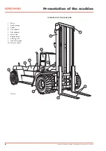
The mast consists of an outer and an inner mast, a fork
carriage, two lift cylinders and two tilt cylinders. The inner
stand section moves along the outer using mast wheels and
support rollers. The mast is mounted on two axles in the
chassis using bearings. The fork carriage is of a rolling type
with sideshift movement and fork spreading.
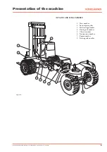
The driver's cabin fulfils international safety standards and is
suspended on the chassis on rubber mounts to protect the
driver from vibrations. Getting into the cabin is done from the
left using the steps in the machine. When the driver seat is
turned 90°, it is also possible to leave the cabin to the right.
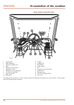
All hydraulic controls for the lifting functions are situated on
the console to the right of the driver seat.
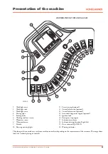
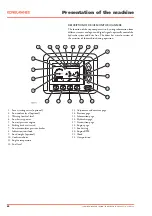
The parking brake, switches for electric optional equipment's,
instruments, gauges and warning indicators are on the front
instrument panel.
Gear change controls, levers for driving direction indicators
and the windscreen wipers are on the steering column.
The electrical system is 24 volt using two heavy duty batteries
connected in line.
Instruction manual SMV 10 600B – 60 1500B Publ. no. 6196.082 1117, Version 02


