OPERATION
EXPLANATION OF COMPONENTS
3-23
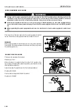
STARTING SWITCH
This switch (1) is used to start or stop the engine.
OFF position
The key can be inserted and removed at this position. When
the key is turned to this position, all electrical circuits are turned
off and the engine stops.
In addition, the parking brake is automatically applied.
ON position
In this position, electric current flows to the charging circuit,
lamp circuit, and accessory circuit.
Keep the starting switch key at the ON position while the
engine is running.
For machines equipped with a prelube system
The engine prelube system (if equipped) is actuated. For details, see “STARTING ENGINE (3-83)“.
If the engine water temperature is below -5°C when the engine is started, the preheating pilot lamp will light up
automatically and preheating will start.
The preheating time differs according to the temperature of the water when the engine is started.
If the preheating pilot lamp lights up, wait for it to go out, then turn the key to the START position.
START position
This is the engine-start position. Keep the key at this position during cranking. Immediately after starting the
engine, release the key. It will automatically return to the ON position.
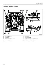
(1)
Starting switch
(19) Room lamp switch
(2)
Transmission cut-off switch
(20) Parking brake switch
(3)
Transmission cut-off set switch
(21) Engine low idling selector switch
(4)
Front and side working lamp switch
(22) Auto-greasing switch (if equipped)
(5)
Rear working lamp switch
(23) Right power window switch
(6)
Transmission auto shift/manual selector switch
(24) Left power window switch
(7)
Active working switch
(25) Hold switch
(8)
Lamp switch
(26) Step lamp switch
(9)
Turn signal switch
(27) Remote positioner RAISE position set switch
(10) Directional selector switch
(if equipped)
(11) Shift up switch
(28) Remote positioner LOWER position set switch
(12) Shift down switch
(if equipped)
(13) Horn button
(29) Remote positioner RAISE/LOWER selector
switch (if equipped)
(14) Hazard lamp switch
(15) Kickdown switch
(30) Machine monitor mode selector switch 1
(16) Front wiper switch
(31) Machine monitor mode selector switch 2
(17) Rear wiper switch
(32) Rear heated wire glass switch
(18) Cigarette lighter
Содержание WA800-3E0
Страница 2: ......
Страница 3: ...FOREWORD 11...
Страница 27: ...SAFETY SAFETY LABELS 2 5 LOCATION OF SAFETY LABELS 2...
Страница 66: ...GENERAL VIEW OPERATION 3 4...
Страница 84: ...EXPLANATION OF COMPONENTS OPERATION 3 22 SWITCHES 3...
Страница 224: ...TROUBLESHOOTING OPERATION 3 162...
Страница 225: ...MAINTENANCE 14 WARNING Please read and make sure that you understand the SAFETY section before reading this section...
Страница 309: ...SPECIFICATIONS 15...
Страница 330: ...HANDLING MACHINES EQUIPPED WITH VHMS ATTACHMENTS OPTIONS 6 20...
Страница 331: ...INDEX 17...
Страница 332: ...INDEX 7 2...
Страница 335: ...COLOPHON 18...


