ATTACHMENTS, OPTIONS
HANDLING AUTO-GREASING SYSTEM
6-5
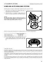
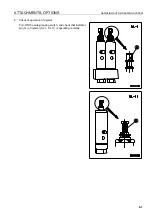
1) One person removes plug (4) from one injector, then
stays there.
This plug (4) is installed to the manifold end of each end
injector.
If air must be bled from the main piping, remove this plug.
2) The other person presses the auto-greasing switch to
start the grease pump.
3) Discharge the grease containing air (milky white in many
cases) from the injector. If normal grease comes out, stop
the grease pump.
4) Tighten plug (4) of the injector to prevent the grease from leaking.
It is impossible to see if the air has been bled by simply checking the pressure gauge. Even if air is mixed in the
grease, the auto-grease system operates since the discharge pressure of the grease pump is high. To see if the
greasing system is working normally, check that the grease pump is balanced and stopped in the specified
(operating) time (60 seconds).
4.
Method of bleeding air from pressure switch This work
shall be performed by two persons.
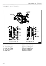
1) Open transmission inspection cover (5) at the rear of the
cab. One person removes pressure switch (7) from block (6),
then stays there.
2) The other person presses the auto-greasing switch to
start the grease pump.
3) Discharge the grease containing air (milky white in many
cases) from the block (6). If normal grease comes out, stop
the grease pump.
4) Install pressure switch (7) to block (6). (Check that grease is not leaking.)
5.
Method of bleeding air from supply line
This work shall be performed by two persons.
1) One person removes supply line pressure gauge (8) from
block (6), then stays there.
2) The other person presses the auto-greasing switch to
start the grease pump.
3) Discharge the grease containing air (milky white in many
cases) from the block (6). If normal grease comes out, stop
the grease pump.
4) Install pressure gauge (8) to block (6). (Check that grease
is not leaking.)
NOTICE
If air is left in the circuit, the grease pressure will not rise
to the specified level or will take a long time to rise to the
specified level, and the injector will not work normally.
View Z
From grease pump
Содержание WA800-3E0
Страница 2: ......
Страница 3: ...FOREWORD 11...
Страница 27: ...SAFETY SAFETY LABELS 2 5 LOCATION OF SAFETY LABELS 2...
Страница 66: ...GENERAL VIEW OPERATION 3 4...
Страница 84: ...EXPLANATION OF COMPONENTS OPERATION 3 22 SWITCHES 3...
Страница 224: ...TROUBLESHOOTING OPERATION 3 162...
Страница 225: ...MAINTENANCE 14 WARNING Please read and make sure that you understand the SAFETY section before reading this section...
Страница 309: ...SPECIFICATIONS 15...
Страница 330: ...HANDLING MACHINES EQUIPPED WITH VHMS ATTACHMENTS OPTIONS 6 20...
Страница 331: ...INDEX 17...
Страница 332: ...INDEX 7 2...
Страница 335: ...COLOPHON 18...

