


Section 10
:
Verification
Series 3700 System Switch/Multimeter Reference Manual
10-18
Document Number: 3700S-901-01 Rev. A / August 2007
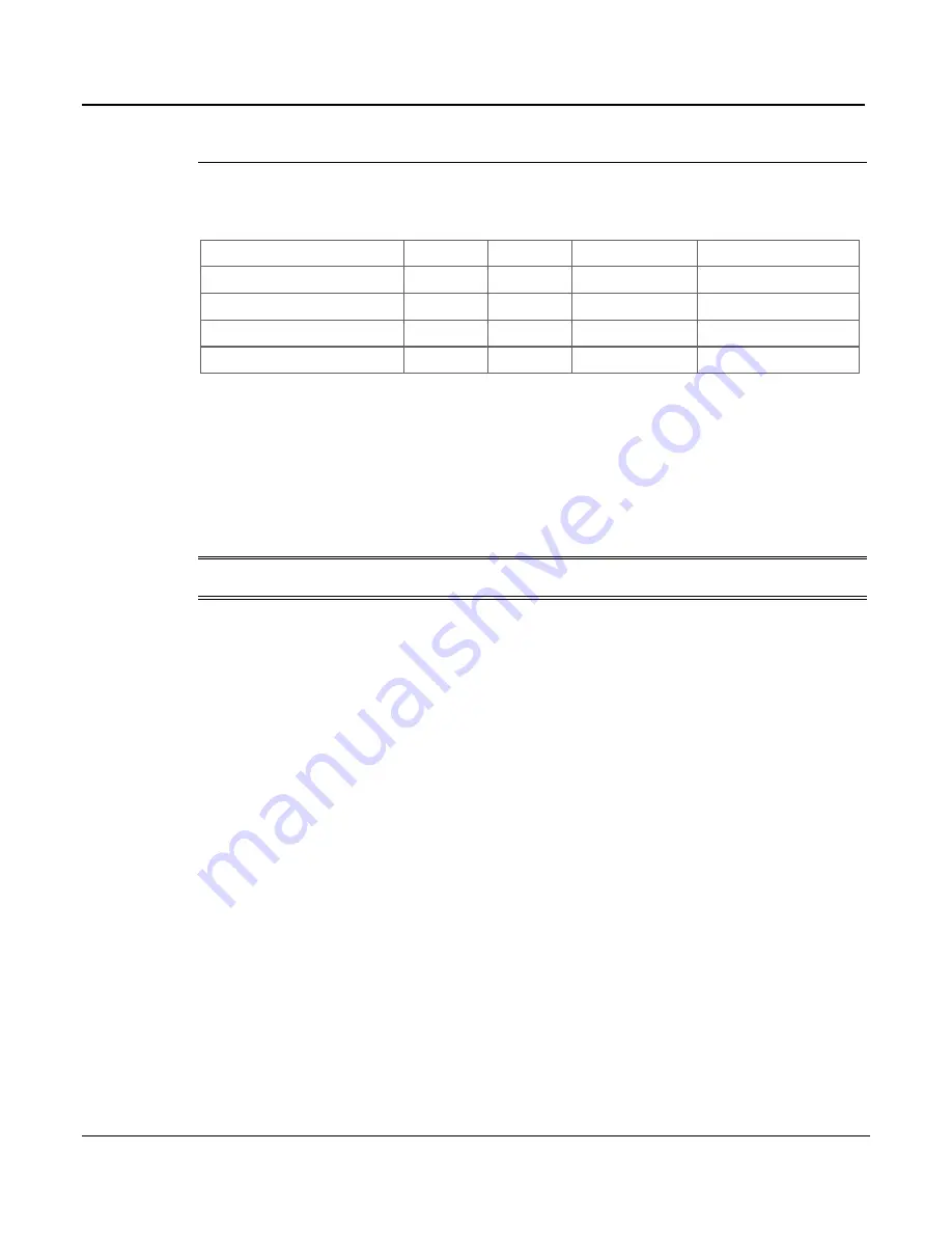
Two-wire resistance verification data
Use the following values to verify the performance of the Series 3700. Actual values are
dependent on published specifications (see
Calculating resistance reading limits
(on page 10-
3)).
Applied Resistance
Range
Current
Lower limit
Upper limit
Verify Res 100k Ohm
1.00E+05
1.00E+05
9.04
1.05
Verify Res 1M Ohm
1.00E+06
1.00E+06
9.05
1.06
Verify Res 10M Ohm
1.00E+07
1.00E+07
9.06
1.07
Verify Res 100M Ohm
1.00E+08
1.00E+08
9.07
1.08
Verifying dry circuit resistance
Check the dry circuit resistance function by connecting accurate resistance values to the Series
3700 analog backplane connector and verify that the displayed readings fall within specified
limits.
CAUTION
Do not exceed 300V peak between INPUT HI and INPUT LO because
instrument damage may occur.
To verify dry circuit resistance accuracy:
1. Using shielded, Teflon-insulated or equivalent cables in a 4-wire configuration, connect the
Series 3700 INPUT and SENSE pins to the calibrator as shown for 100
-10M
ranges.
2. Set the calibrator for 4-wire resistance with external sense on.
3. Select the Series 3700 4-wire resistance function.
4. Select the SLOW integration rate with the
RATE
key.
5. Enable dry circuit resistance function (see Enabling/disabling dry circuit ohms in the User's
manual).
6. Set the Series 3700 for the 100
range, and make sure the FILTER is on. Enable OC+
(offset-compensated ohms). (Use OC+ for 100
range verification). See Enabling/disabling
offset-compensated ohms in the User's manual.
7. Recalculate reading limits based on actual calibrator resistance values.