


Section 10
:
Verification
Series 3700 System Switch/Multimeter Reference Manual
10-16
Document Number: 3700S-901-01 Rev. A / August 2007
7. Source the nominal full-scale resistance values for the 100
-10M
ranges summarized in
the Resistance verification table. Recalculate the limits based on the actual value of the
resistor and verify the reading is within the calculated limits.
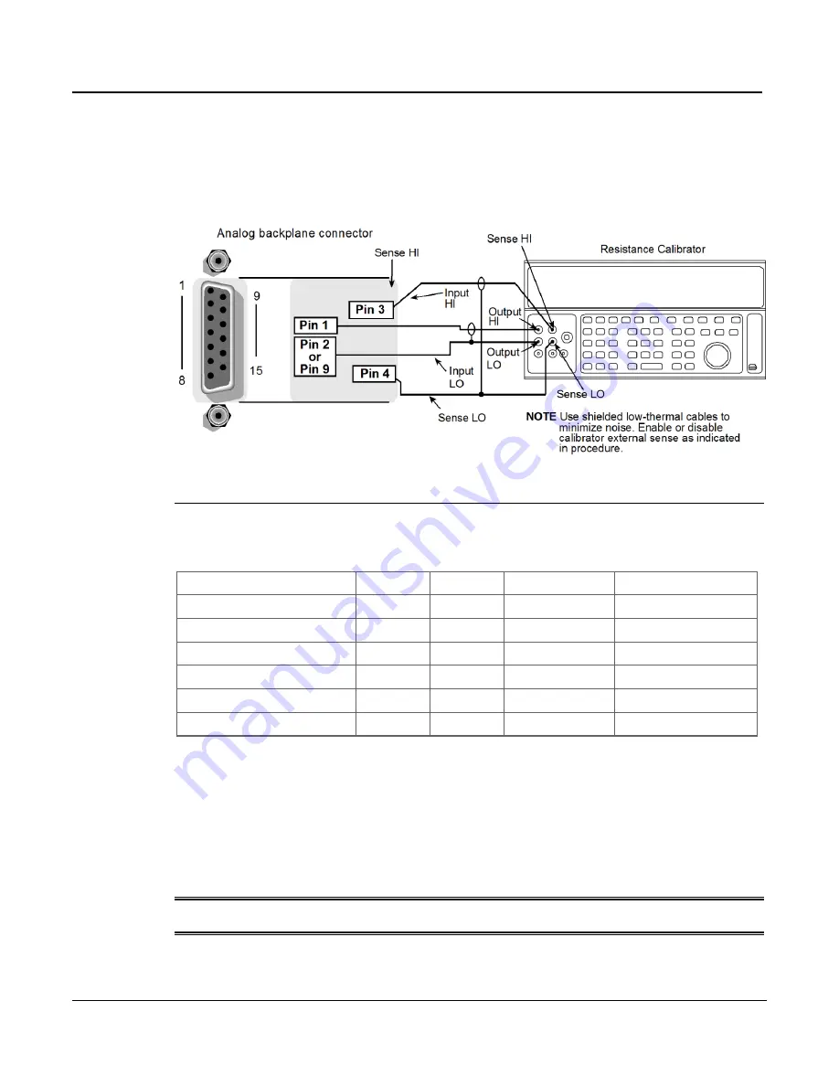
Figure 10-7: Verifying four-wire resistance
Four-wire resistance verification data
Use the following values to verify the performance of the Series 3700. Actual values are
dependent on published specifications (see
Calculating resistance reading limits
(on page 10-
3)).
Applied Resistance
Range
Value
Lower limit
Upper limit
Verify Res 100 Ohm
1.00E+02
1.00E+02
9.01
1.02
Verify Res 1k Ohm
1.00E+03
1.00E+03
9.02
1.03
Verify Res 10k Ohm
1.00E+04
1.00E+04
9.03
1.04
Verify Res 100k Ohm
1.00E+05
1.00E+05
9.04
1.05
Verify Res 1M Ohm
1.00E+06
1.00E+06
9.05
1.06
Verify Res 10M Ohm
1.00E+07
1.00E+07
9.06
1.07
Verifying two-wire resistance
Check the normal resistance function by connecting accurate resistance values to the Series
3700 analog backplane connector and verify that the displayed readings fall within specified
limits.
CAUTION
Do not exceed 1000V peak between INPUT HI and INPUT LO because
instrument damage may occur.