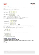
2.2.4 Setting of the Rate of Turn Filter Constant
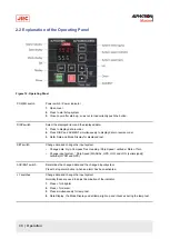
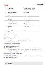
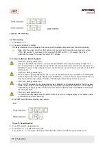
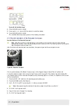
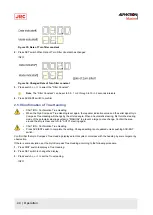
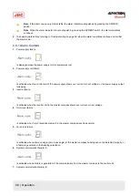
1. Press the SET button when the Rate of Turn Filter Constant is changed.
2. Press
▼or▲
to select the Filter Constant.
Note The Filter Constant can be set to 0.5, 1 or 2 through to 10 in 2second steps.
3. Press ACK/ENT to enter the selection.
2.3 Data Indications
Explanations of indicated data.
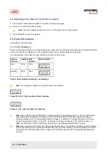
2.3.1 True Heading 1
When True Heading of the sensor is selected as system, either the Gyro Compass True Heading or the external heading
sensor True Heading, is displayed. For the system selection, refer to System Selection on page 45
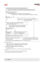
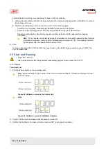
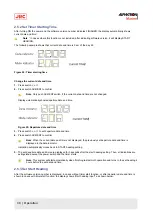
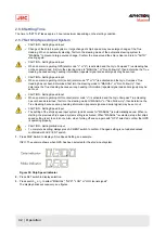
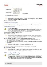
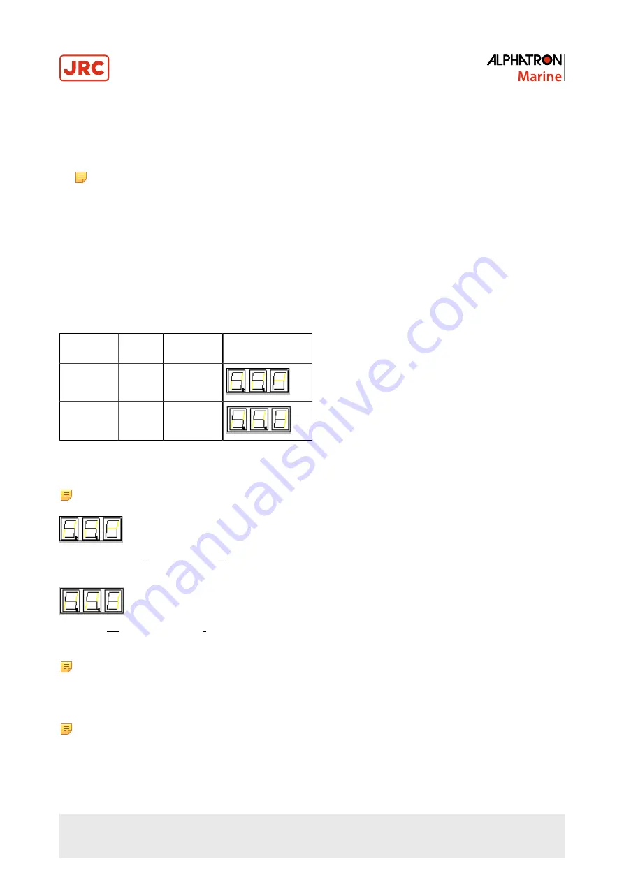
The indicated data in the data and mode indicators are shown in table below.
System
Selection
Heading Data
Indicator
Mode Indicator
Gyro
123.4
123.4
Heading
345.6
345.6
Table 8: Data and Mode Indicators True Heading 1
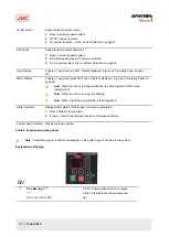
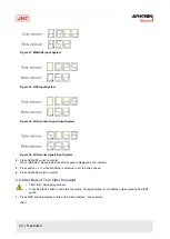
Note The meaning of a display of a “mode indicator” is as follows:
Figure 20: S.S.G = Steering Sensor Gyro Compass
Figure 21: Gyt = Gyro Compass true heading
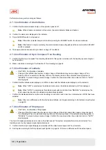
Note When a GPS communication failure, LOG (serial signal) communication failure, or LOG (contact) failure
is generated, the data indicator is blinking. If "GYRO" system is selected at the time, operate according to
Corrective Measures GPS Communication Failure on page 51 is activated, Corrective Measures LOG (serial
signal) Communication Failure on page 51 is activated, or Corrective Measures LOG (contact) Failure on
page 52 is activated, in chapter Operations, because the True Heading determination is required.
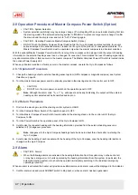
Note When communication failure with "the external heading sensor" is generated, the data indicator is blinking.
If "External heading sensor" system is selected at the time, operate according to Corrective Measures External
Heading Sensor Communication Failure on page 51 is activated, because the True Heading determination is
required.
33 | Operation
Содержание Alpatron AlphaMidiCourse
Страница 1: ...AlphaMidiCourse Gyro Compass Installation and Operation Manual www jrc am ...
Страница 68: ...5 1 1 Outline Control Unit One Gyro Compass System Figure 41 Control Box 68 Appendices ...
Страница 69: ...5 1 2 Operating Panel Figure 42 Operating Panel 69 Appendices ...
Страница 70: ...5 1 3 Master Compass Figure 43 Main Unit 70 Appendices ...
Страница 71: ...Figure 44 Open Gyro Compass 71 Appendices ...
Страница 73: ...5 1 5 Connection Diagram Figure 46 Connection Diagram 73 Appendices ...
Страница 74: ...5 1 6 Cable Diagram Figure 47 Cable Diagram 74 Appendices ...
Страница 75: ...5 1 7 Installation Drawing Figure 48 Installation Drawing 75 Appendices ...
Страница 76: ...5 1 8 Terminal Board Figure 49 Terminal Board 76 Appendices ...

