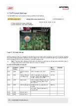
S1
Standard
Setting
Details
Function
Read
Timing
Remarks
NO.7
[OFF]
Master Compass
Installation
[ON] : Master Compass is installed
reversely
180˚
Start Up
NO.8
[OFF]
Do Not Touch
*
Table 4: MCC pwb switch assign
* For MCC pwb check mode : S1 all [ON].
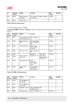
Interval Setting NMEA: 100msec, or 200msec, or 1sec.¹ Set standard to off, for Pendulum Ferry use external
Interface!
ICIF
pwb S1
Standard
Setting
Details
Function
Read
Timing
Remarks
NO.1
[ON]
Connect External
Power Supply Unit
[OFF] :yes [ON:
no
Start Up
NO.2
[OFF]
Master Compass
type
[OFF] : Standard
Type [ON] : HSC
type
Start Up
NO.3
[OFF]
Control Box type
[OFF] : Type S
[ON] : Type D
(dual gyro)
Start Up
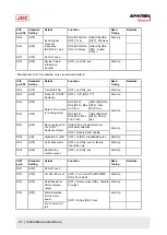
NO.4
[OFF]
No.2 Gyro or not
[OFF] : No [ON] :
Yes
Start Up
NO.5
[OFF]
NO.6
[OFF]
External Sensor
Connection
NO5.[OFF],
NO6.[OFF] : Non
NO5. [ON],
NO6. [OFF] :
External Sensor
Connection
Start Up
NO.7
[OFF]
Serial Signal Select [OFF] :
IEC61162-2
[on] : Tokimec
format
Start Up
NO.8
[OFF]
Alarm Output
Setup
[OFF] : All alarm
output [ON] :
only power fail
Start Up
Table 5: ICIF PWB Dip Switch assign :
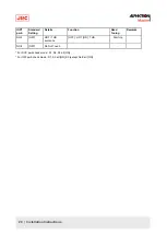
ICIF
pwb S2
Standard
Setting
Details
Function
Read
Timing
Remarks
NO.1
[OFF]
For debugging (Do
Not Touch)
-
NO.2
[OFF]
For debugging (Do
Not Touch)
-
NO.3
[ON[
Alphatron or other
[OFF] : Standard [ON] :
AlphaMidiCourse¹
NO.4
[OFF]
Pendulum Ferry
[OFF] : No [ON] : Yes
Start Up
26 | Installation Instructions
Содержание Alpatron AlphaMidiCourse
Страница 1: ...AlphaMidiCourse Gyro Compass Installation and Operation Manual www jrc am ...
Страница 68: ...5 1 1 Outline Control Unit One Gyro Compass System Figure 41 Control Box 68 Appendices ...
Страница 69: ...5 1 2 Operating Panel Figure 42 Operating Panel 69 Appendices ...
Страница 70: ...5 1 3 Master Compass Figure 43 Main Unit 70 Appendices ...
Страница 71: ...Figure 44 Open Gyro Compass 71 Appendices ...
Страница 73: ...5 1 5 Connection Diagram Figure 46 Connection Diagram 73 Appendices ...
Страница 74: ...5 1 6 Cable Diagram Figure 47 Cable Diagram 74 Appendices ...
Страница 75: ...5 1 7 Installation Drawing Figure 48 Installation Drawing 75 Appendices ...
Страница 76: ...5 1 8 Terminal Board Figure 49 Terminal Board 76 Appendices ...

