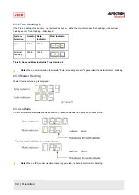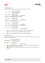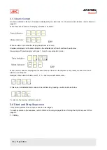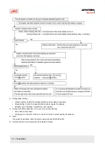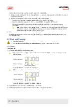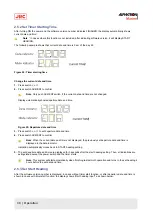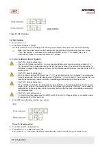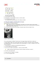
Note If the alarm occurs only momentarily, the alarm indicator extinguishes by pressing the ACK/ENT
switch.
Note When the alarm indicator did not extinguish by pressing the ACK/ENT switch, the alarm conditions
continues.
2. Take appropriate actions referring to Troubleshooting on page 59, when the alarm conditions continue and confirm
the alarm code.
2.9.1 Alarm Content
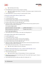
1. Power supply failure.
Is displayed when the power supply for this system was lost.
2. Power supply unit failure.
Is activated when the control unit of the power supply shows over current or over voltage, or the power supply output
falls away.
3. Inverter failure.
Is activated when the inverter unit in the master compass shows over current or over voltage.
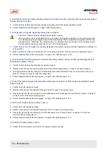
4. Rotor level failure.
Is activated when "rotor”(sensitive element) in the master compass level is abnormal.
5. Zero cross failure.
Is activated when reference angle (zero cross angle) of the master compass heading can not be detected properly, or
a failure is generated in the heading calculation.
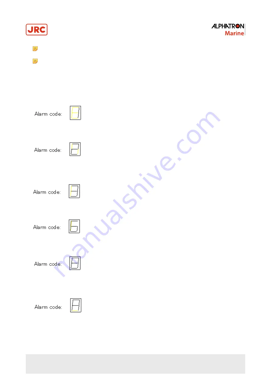
6. System communication failure (1).
Is activated when a failure is generated in the communication from the master compass to the control unit.
7. System communication failure (2).
48 | Operation
Содержание Alpatron AlphaMidiCourse
Страница 1: ...AlphaMidiCourse Gyro Compass Installation and Operation Manual www jrc am ...
Страница 68: ...5 1 1 Outline Control Unit One Gyro Compass System Figure 41 Control Box 68 Appendices ...
Страница 69: ...5 1 2 Operating Panel Figure 42 Operating Panel 69 Appendices ...
Страница 70: ...5 1 3 Master Compass Figure 43 Main Unit 70 Appendices ...
Страница 71: ...Figure 44 Open Gyro Compass 71 Appendices ...
Страница 73: ...5 1 5 Connection Diagram Figure 46 Connection Diagram 73 Appendices ...
Страница 74: ...5 1 6 Cable Diagram Figure 47 Cable Diagram 74 Appendices ...
Страница 75: ...5 1 7 Installation Drawing Figure 48 Installation Drawing 75 Appendices ...
Страница 76: ...5 1 8 Terminal Board Figure 49 Terminal Board 76 Appendices ...

