INFO:
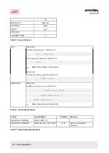
Stand alone type (Model - I)
Voltage
The system where both the master compass and the control unit are
not built into the automatic steering system.
Input terminals of the emergency power supply (between 1B+ and
1B- of the external terminal board TB3-5 and TB3-6.
24 V DC, within -20 % to +30 %
3. Contact Alphatron Marine service engineer, or agent, immediately after checking steps 1 and 2 above.
4.6.5.2 Power Supply Failure (alarm code 2)
1. Turn OFF the power switch.
2. Wait approx. 20 seconds before turning ON again.
3. Take action according to Start on page 38, if no alarm code 2 was activated.
4. Turn OFF the power switch and request repair from Alphatron Marine service engineer, or agent, if an alarm is
activated again in alarm code 2.
4.6.5.3 Inverter Failure (alarm code 3)
•
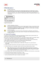
CAUTION - Not all repeaters operate
•
When checking fuses, turn OFF the power switch, and disconnect the power cable from the ship’s distribution
terminal board.
1. Turn OFF the power switch.
2. Turn ON again after approx. 20 seconds.
3. Take action according to Start on page 38, if no alarm code 3 was activated.
4. Check the inverter fuse (F1-12A), located in the base of the master compass, Master Compass on page 70, if an
alarm is activated again in alarm code 3.
5. Turn OFF the power switch and request repair from Alphatron Marine service engineer, or agent.
4.6.5.4 Rotor Level Failure (alarm code 6)
•
CAUTION - Rotor Level Failure (alarm code 6)
•
Turn OFF the power switch.
1. Turn OFF the power switch.
2. Turn ON again after approx. 20 seconds.
3. Take action according to Start on page 38.
4. Observe the heading of the Gyro Compass for two hours or more.
5. Contact Alphatron Service Engineer, or agent, after checking heading of the Gyro Compass.
4.6.5.5 Zero Cross Failure (alarm code 8)
•
CAUTION - Zero Cross Failure (alarm code 8)
•
Determination of the Gyro Compass True Heading when alarm code 8 is activated, may cause a large
change of the True Heading. During automatic navigation, take great care, because a large course change
may have happened.
1. Press DISP switch.
Note Ensure SSG or GYT is shown in Mode Display.
61 | Maintenance
Содержание Alpatron AlphaMidiCourse
Страница 1: ...AlphaMidiCourse Gyro Compass Installation and Operation Manual www jrc am ...
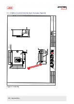
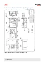
Страница 68: ...5 1 1 Outline Control Unit One Gyro Compass System Figure 41 Control Box 68 Appendices ...
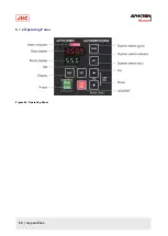
Страница 69: ...5 1 2 Operating Panel Figure 42 Operating Panel 69 Appendices ...
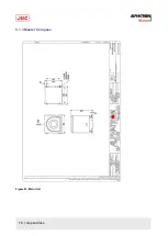
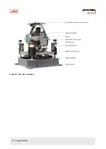
Страница 70: ...5 1 3 Master Compass Figure 43 Main Unit 70 Appendices ...
Страница 71: ...Figure 44 Open Gyro Compass 71 Appendices ...
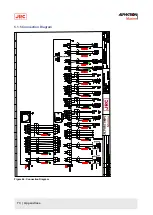
Страница 73: ...5 1 5 Connection Diagram Figure 46 Connection Diagram 73 Appendices ...
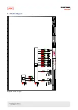
Страница 74: ...5 1 6 Cable Diagram Figure 47 Cable Diagram 74 Appendices ...
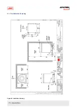
Страница 75: ...5 1 7 Installation Drawing Figure 48 Installation Drawing 75 Appendices ...
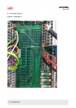
Страница 76: ...5 1 8 Terminal Board Figure 49 Terminal Board 76 Appendices ...

