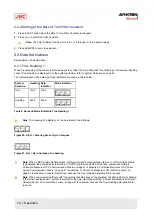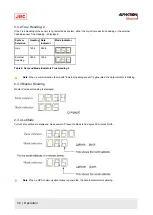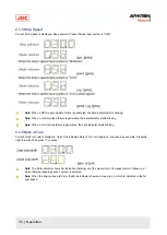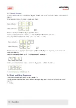
2.5.2 Set Timer Starting Time
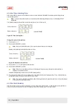
After turning ON the power and the software version number indicates FINISHED, the display automatically shows
current date and time¹.
Note ¹ In cases where this function is not included, after indicating software version, it will display START
HEADING.
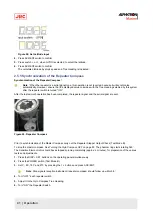
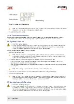
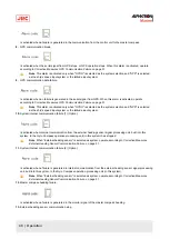
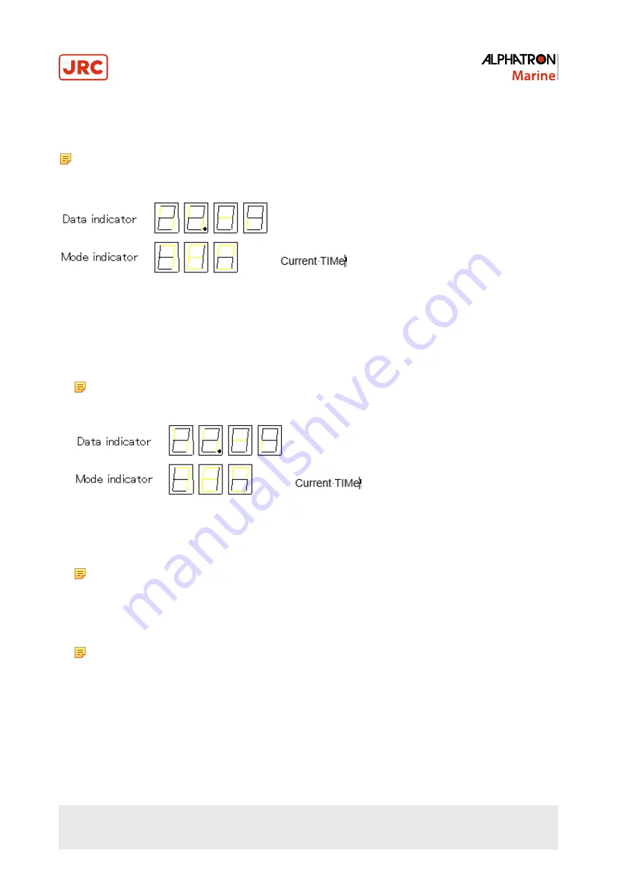
The following example shows that current date and time is 9 am of the day 22.
Figure 24: Timer starting time
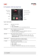
Change the current date and time.
1. Press switch
▲,
or
▼.
2. Press switch ACK/ENT to confirm.
Note Only push ACK/ENT switch, if the current date and time are not changed.
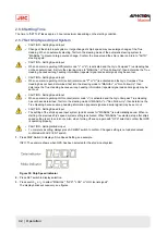
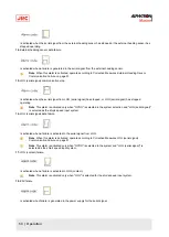
Display automatically shows departure date and time.
Figure 25: Departure date and time
3. Press switch
▲,
or
▼
to set departure date and time.
4. Press switch ACK/ENT to confirm.
Note When the current date and time is not displayed, the previously set departure date and time is
displayed in the data indicator.
Indication automatically moves back to START heading setting.
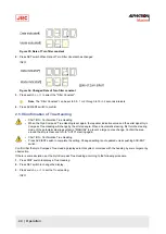
5. The set departure date and time are displayed for 3 seconds after the start heading setting. Then, all indications are
extinguished except the power switch and the timer starts.
Note This system will start automatically when finishing last azimuth operation and turns to the set heading 4
hours before the set date and time.
2.5.3 Set Start Heading
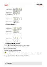
After the software version number is displayed, in cases without timer start function, or after departure date and time is
shown in cases with timer start function, the display shows "start heading input", as shown below.
39 | Operation
Содержание Alpatron AlphaMidiCourse
Страница 1: ...AlphaMidiCourse Gyro Compass Installation and Operation Manual www jrc am ...
Страница 68: ...5 1 1 Outline Control Unit One Gyro Compass System Figure 41 Control Box 68 Appendices ...
Страница 69: ...5 1 2 Operating Panel Figure 42 Operating Panel 69 Appendices ...
Страница 70: ...5 1 3 Master Compass Figure 43 Main Unit 70 Appendices ...
Страница 71: ...Figure 44 Open Gyro Compass 71 Appendices ...
Страница 73: ...5 1 5 Connection Diagram Figure 46 Connection Diagram 73 Appendices ...
Страница 74: ...5 1 6 Cable Diagram Figure 47 Cable Diagram 74 Appendices ...
Страница 75: ...5 1 7 Installation Drawing Figure 48 Installation Drawing 75 Appendices ...
Страница 76: ...5 1 8 Terminal Board Figure 49 Terminal Board 76 Appendices ...

