1.5 Connecting the AlphaMidiCourse
Refer Connection Diagram and Cable Diagram for cable connections Figure 46: Connection Diagram on page 73,
Figure 47: Cable Diagram on page 74.
1. Connect power and signaling cables as indicated in the connection diagram.
2. Use wire straps to fasten cables.
CABLE SPECIFICATIONS - See Connection Diagram and Cable Diagram Figure 46: Connection Diagram on page
73, Figure 47: Cable Diagram on page 74.
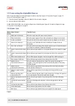
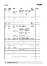
1.6 Alarm List
Alarm
Code
Alarm Content
Possible Cause
1
Main power is abnormal
When the main power (AC power source) was lost.
2
Power is abnormal
When the power supply in the control unit went over-voltage or over-current.
3
Inverter is abnormal
When the inverter in the master compass went over-voltage or over-current.
6
Rotor level is abnormal
When the "rotor” (Sensitive Element) in the Master Compass behaves
abnormally.
8
Zero cross is abnormal
When the reference heading of the master compass was not detected properly
or an failure is generated in heading calculation.
A
System communication failure
(1)
When a failure is generated in communication function of the master compass.
b
System communication failure
(2)
When a failure is generated in communication function of the control unit.
c
GPS communication break
When GPS operation stopped or the serial signal from GPS has stopped.
d
Abnormality of GPS data
When a failure is generated in the serial signal from the GPS.
E
System internal
communication failure (1)
When the External Heading Sensor Signal Processing Unit stopped its
operation, or the serial signal from the External Heading Sensor Processing
Unit has stopped.
F
System internal
communication failure (2)
When a failure is generated in the serial signal from the External heading
sensor signal processing unit.
G
Master compass heading
failure
When a failure is generated in the heading monitor signal of the master
compass.
L
External heading sensor
communication off
When the External heading sensor signal processing unit stopped its operation,
or the serial signal of the external sensor has stopped.
n
External heading Sensor data
failure
When a failure is generated in the serial signal from the External heading
sensor.
P
LOG (serial) communication
off
When the LOG stopped its operation, or the serial signal from LOG has
stopped.
U
LOG (serial) data failure
When a failure is generated in the serial signal from LOG.
u
LOG contact failure
When a failure is generated in the LOG contact.
r
E5V failure
When a failure is generated in the power supply for the serial signal.
Table 3:
24 | Installation Instructions
Содержание Alpatron AlphaMidiCourse
Страница 1: ...AlphaMidiCourse Gyro Compass Installation and Operation Manual www jrc am ...
Страница 68: ...5 1 1 Outline Control Unit One Gyro Compass System Figure 41 Control Box 68 Appendices ...
Страница 69: ...5 1 2 Operating Panel Figure 42 Operating Panel 69 Appendices ...
Страница 70: ...5 1 3 Master Compass Figure 43 Main Unit 70 Appendices ...
Страница 71: ...Figure 44 Open Gyro Compass 71 Appendices ...
Страница 73: ...5 1 5 Connection Diagram Figure 46 Connection Diagram 73 Appendices ...
Страница 74: ...5 1 6 Cable Diagram Figure 47 Cable Diagram 74 Appendices ...
Страница 75: ...5 1 7 Installation Drawing Figure 48 Installation Drawing 75 Appendices ...
Страница 76: ...5 1 8 Terminal Board Figure 49 Terminal Board 76 Appendices ...

