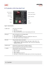
GYRO switch
System selection switch (Gyro).
1. Press to select required system.
2. "GYRO" system is select.
3. For system selection, refer to System Selection on page 45
EXT switch
System selection switch (External).
1. Press to select required system.
2. "External Heading Sensor" system is selected.
3. For the system select, refer to System Selection on page 45
Data Display
4 figures, 7 segments red LED : Data is displayed. (Figure 42: Operating Panel on page
69)
Mode Display
3 figures, 7 segments green LED: Type of data is displayed. (Figure 42: Operating Panel on
page 69)
Note When the rotor is in stopped situation, the dot at right end of the mode
indicator is lit.
Note When the rotor is running, it is blinking.
Note When in the follow up situation, it is extinguished.
Alarm Indicator
Displays alarm status. It blinks when an alarm is generated.
1. Press ACK/ENT to stop alarm.
2. If cause of alarm has not been resolved, it continues blinking.
System select Indicator Displays selected system.
Table 6: Functions Operating Panel
Note ¹ Selectable system is different depending on the system type connected to this system.
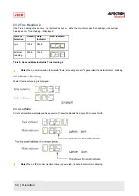
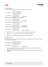
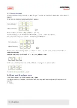
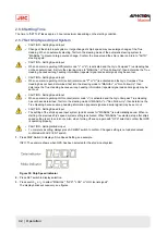
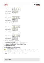
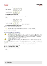
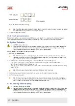
Explanation of Display:
Press
DISP
1
True Bearing 1: ***
***.*
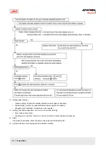
S.S.G or S.S.E or GYt
S.S.G = Steering.Sensor.Gyro-compass
S.S.E = Steering.Sensor.External sensor
Gyt
31 | Operation
Содержание Alpatron AlphaMidiCourse
Страница 1: ...AlphaMidiCourse Gyro Compass Installation and Operation Manual www jrc am ...
Страница 68: ...5 1 1 Outline Control Unit One Gyro Compass System Figure 41 Control Box 68 Appendices ...
Страница 69: ...5 1 2 Operating Panel Figure 42 Operating Panel 69 Appendices ...
Страница 70: ...5 1 3 Master Compass Figure 43 Main Unit 70 Appendices ...
Страница 71: ...Figure 44 Open Gyro Compass 71 Appendices ...
Страница 73: ...5 1 5 Connection Diagram Figure 46 Connection Diagram 73 Appendices ...
Страница 74: ...5 1 6 Cable Diagram Figure 47 Cable Diagram 74 Appendices ...
Страница 75: ...5 1 7 Installation Drawing Figure 48 Installation Drawing 75 Appendices ...
Страница 76: ...5 1 8 Terminal Board Figure 49 Terminal Board 76 Appendices ...

