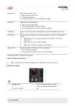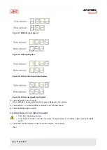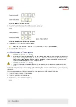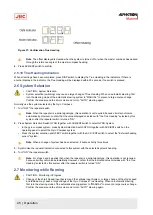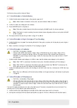
2.3.2 True Heading 2
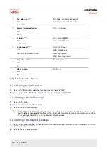
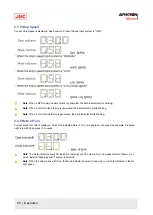
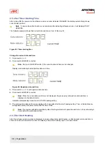
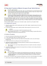
If the True Heading of the sensor is not selected as system, either the Gyro Compass true heading or the external
heading sensor True Heading, is displayed.
System
Selection
Heading Data
Indicator
Mode Indicator
Gyro
123.4
345.6
External
Heading
345.6
123.4
Table 9: Data and Mode Indicators True Heading 2
Note When a communication failure with "External heading sensor" is generated, the data indicator is blinking.
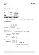
2.3.3 Master Heading
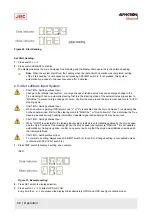
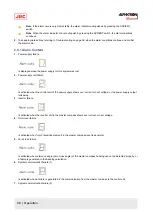
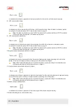
Master Compass Heading is displayed.
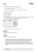
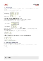
2.3.4 Latitude
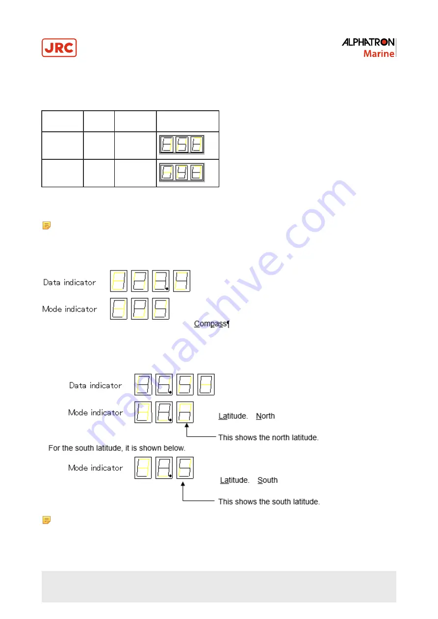
Current ship Latitude is displayed. See example: Present Latitude is 36 degree 50 minutes North.
Note When a GPS communication failure is generated, the data indicator starts blinking.
34 | Operation
Содержание Alpatron AlphaMidiCourse
Страница 1: ...AlphaMidiCourse Gyro Compass Installation and Operation Manual www jrc am ...
Страница 68: ...5 1 1 Outline Control Unit One Gyro Compass System Figure 41 Control Box 68 Appendices ...
Страница 69: ...5 1 2 Operating Panel Figure 42 Operating Panel 69 Appendices ...
Страница 70: ...5 1 3 Master Compass Figure 43 Main Unit 70 Appendices ...
Страница 71: ...Figure 44 Open Gyro Compass 71 Appendices ...
Страница 73: ...5 1 5 Connection Diagram Figure 46 Connection Diagram 73 Appendices ...
Страница 74: ...5 1 6 Cable Diagram Figure 47 Cable Diagram 74 Appendices ...
Страница 75: ...5 1 7 Installation Drawing Figure 48 Installation Drawing 75 Appendices ...
Страница 76: ...5 1 8 Terminal Board Figure 49 Terminal Board 76 Appendices ...

