2.2 Explanation of the Operating Panel
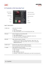
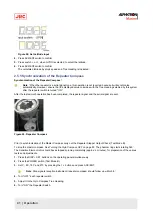
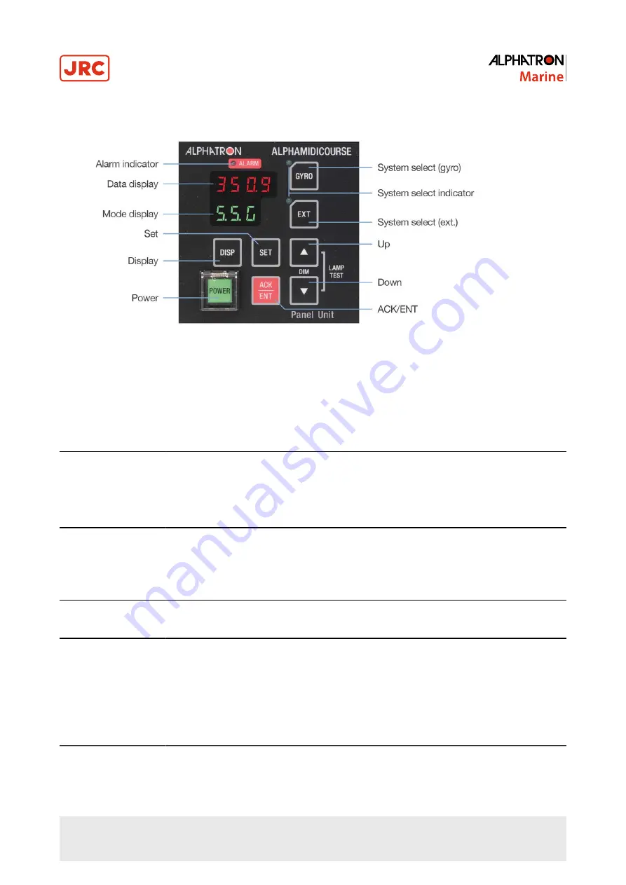
Figure 19: Operating Panel
POWER switch
Power switch / Power indicator
1. Open cover
2. Press to start/stop system
3. Close cover after start-up, so as not to inadvertently push the button.
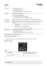
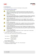
DISP switch
Select the displayed item and the displayed data.
1. Press to display data in order.
2. Press DISP and ACK/ENT simultaneously to display data in reverse order.
3. Refer Data and Mode Display for displayed text.
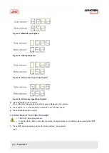
SET switch
Change data and change the input system.
•
Change data: Gyro Compass True Heading / Ship Speed / Latitude / Rate of Turn.
•
Change input system: ¹ Ship Speed (MANUAL, GPS, LOG and LOG (serial signal))
Latitude (GYRO and GPS).
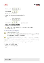
ACK/ENT switch
Determines the changed data and the changed input system.
Press to stop alarm buzzer when an alarm has been activated.
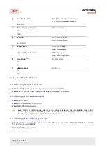
▲▼
switches
Change data and change the input system.
Normally these are used to adjust illumination of the indicator.
1. Press
▲
for brighter.
2. Press
▲
for darker.
3. Press simultaneously for lamp test.
4. Data Display, the Mode Display and all lamps light up and it buzzes during the lamp test.
30 | Operation
Содержание Alpatron AlphaMidiCourse
Страница 1: ...AlphaMidiCourse Gyro Compass Installation and Operation Manual www jrc am ...
Страница 68: ...5 1 1 Outline Control Unit One Gyro Compass System Figure 41 Control Box 68 Appendices ...
Страница 69: ...5 1 2 Operating Panel Figure 42 Operating Panel 69 Appendices ...
Страница 70: ...5 1 3 Master Compass Figure 43 Main Unit 70 Appendices ...
Страница 71: ...Figure 44 Open Gyro Compass 71 Appendices ...
Страница 73: ...5 1 5 Connection Diagram Figure 46 Connection Diagram 73 Appendices ...
Страница 74: ...5 1 6 Cable Diagram Figure 47 Cable Diagram 74 Appendices ...
Страница 75: ...5 1 7 Installation Drawing Figure 48 Installation Drawing 75 Appendices ...
Страница 76: ...5 1 8 Terminal Board Figure 49 Terminal Board 76 Appendices ...

