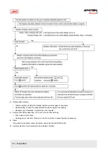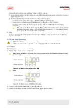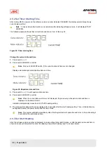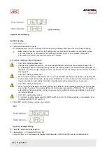
2.9.2 Corrective Measures GPS Communication Failure
•
CAUTION - Corrective Measures GPS Communication Failure
•
When an alarm related to GPS (alarm code "c" or "d") is activated and the Gyro Compass' True Heading has
not been determined, first turn the steering mode to "MANUAL", or "Non Follow Up", then determine the True
Heading, because wrong heading information (repeater signal and serial signal) may be sent out.
•
CAUTION - Corrective Measures GPS Communication Failure
•
Determination of the True Heading may cause large change of sent heading information. During automatic
navigation, great care should be taken, because large course changes may have happened.
The True Heading, which currently is displayed and sent is the corrected value based on the corrected value immediately
before the GPS alarm was activated.
1. Select other mode than GPS, when GPS has been selected as the ship's speed input system.
Note Refer to Set Ship Speed Input System on page 42.
2. Select other mode than GPS, when GPS has been selected as the latitude input system.
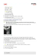
The True Heading indication is blinking showing the True Heading calculated, based on the changed ship's speed
and latitude
3. Press ACK/ENT switch to confirm True Heading.
The True Heading indication lights up and the True Heading sent is also confirmed.
2.9.3 Corrective Measures External Heading Sensor Communication Failure
•
CAUTION - Corrective Measures EXTERNAL HEADING SENSOR Communication Failure
•
When an alarm regarding the EXTERNAL HEADING SENSOR (alarm code "E", "F", "L" and "N") is activated,
the heading information (repeater signal and serial signal) immediately before the alarm generated is sent.
First turn the steering mode to "MANUAL" or "Non Follow Up", and then determine the True Heading. Once
True Heading has been determined, the system's heading is sent out.
•
CAUTION - Corrective Measures EXTERNAL HEADING SENSOR Communication Failure
•
Determination of the True Heading may cause large change of sent heading information. During automatic
navigation, great care should be taken, because large course changes may have happened.
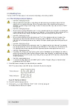
When the alarm related to the External Heading Sensor is activated, the True Heading of the data indicator is blinking.
The True Heading that is currently displayed on the indicator was the True Heading before an alarm was activated.
When the alarm has been recovered the received heading will be indicated.
When the alarm continues, the True Heading cannot be determined.
The True Heading sent out, is the heading immediately before the alarm was activated.
1. Confirm that the alarm related to the external heading sensor has been recovered.
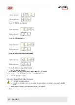
2. Press the ACK/ENT switch as the True Heading is displayed in the indicator.
The External Heading Sensor True Heading indicator for the True Heading lights up and the sent out True Heading is
the confirmed true heading.
2.9.4 Corrective Measures LOG (serial signal) Communication Failure
•
CAUTION - Setting Speed Input
•
When an alarm regarding LOG (serial) (alarm code "P" or "U") is activated and the Gyro Compass' True
Heading has not been determined, first turn the steering mode to "MANUAL" or "Non Follow Up", then
determine the True Heading, because wrong heading information (repeater signal and serial signal) may be
sent out.
•
CAUTION - Corrective Measures LOG Communication Failure
•
Determination of the True Heading may cause large change of sent heading information. During automatic
navigation, great care should be taken, because large course changes may have happened.
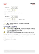
When a failure related to LOG (serial signal) is activated, the data indicator is blinking.
51 | Operation
Содержание Alpatron AlphaMidiCourse
Страница 1: ...AlphaMidiCourse Gyro Compass Installation and Operation Manual www jrc am ...
Страница 68: ...5 1 1 Outline Control Unit One Gyro Compass System Figure 41 Control Box 68 Appendices ...
Страница 69: ...5 1 2 Operating Panel Figure 42 Operating Panel 69 Appendices ...
Страница 70: ...5 1 3 Master Compass Figure 43 Main Unit 70 Appendices ...
Страница 71: ...Figure 44 Open Gyro Compass 71 Appendices ...
Страница 73: ...5 1 5 Connection Diagram Figure 46 Connection Diagram 73 Appendices ...
Страница 74: ...5 1 6 Cable Diagram Figure 47 Cable Diagram 74 Appendices ...
Страница 75: ...5 1 7 Installation Drawing Figure 48 Installation Drawing 75 Appendices ...
Страница 76: ...5 1 8 Terminal Board Figure 49 Terminal Board 76 Appendices ...

