34
• CONTACT –
press this button to access the contact screen, as shown in figure 30, where it is possible
to view the manufacturer's data.
• MEMORY SETTING –
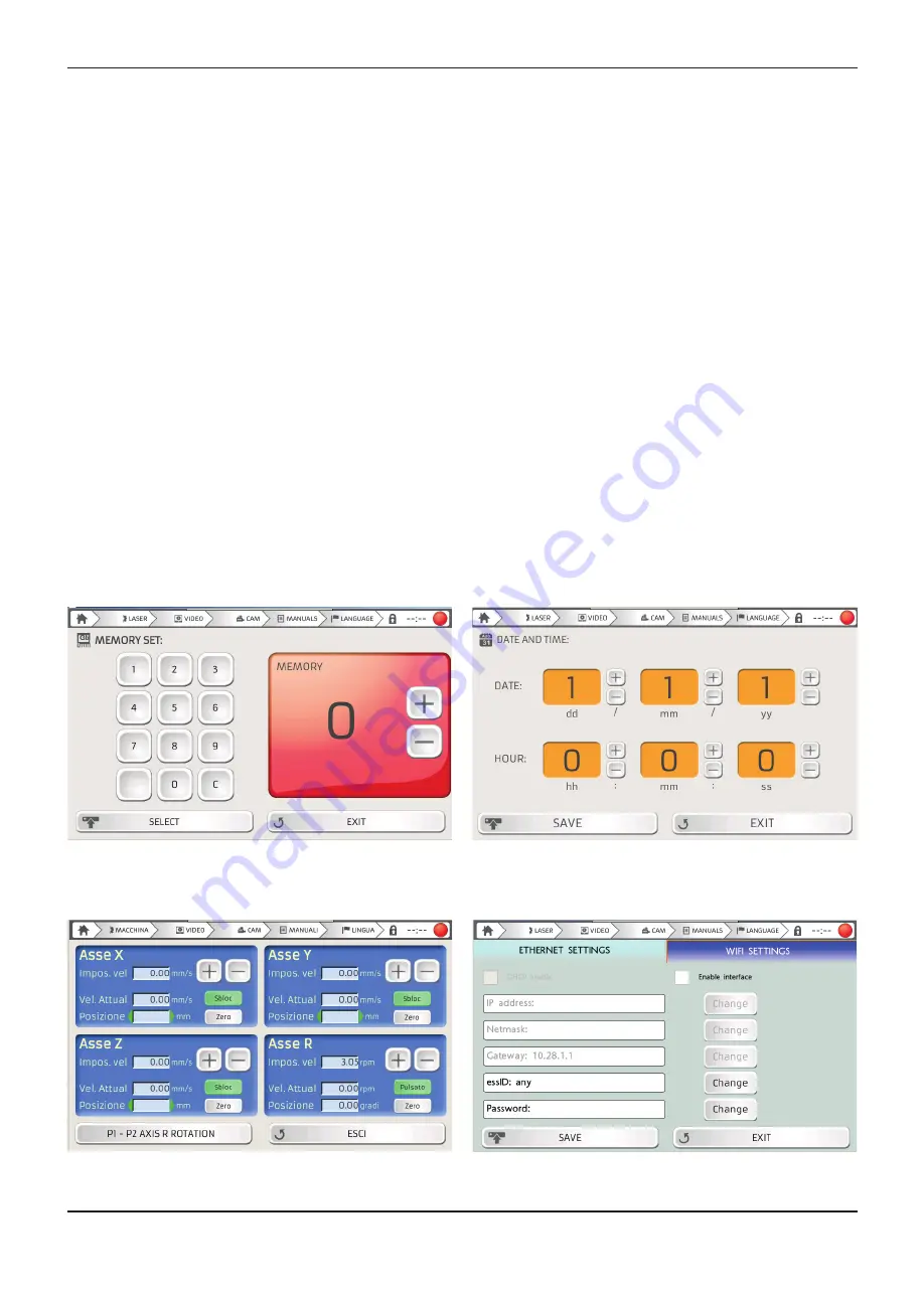
you can save up to 99 combinations of parameters and use this screen to select
one of the saved ones (figure 31).
• MOTOR CONTROL –
press this button to access the machine axes control screen. In this window
it is possible to decide whether to lock or unlock each axis, set the respective displacement speed,
expressed in mm/s (millimetres per second), or return it to the 0 position by pressing the RESET key.
Each axis is set separately from the others. The R axis is active only when the spindle is connected
(Figure 32).
• DATE AND TIME –
access this window to set the date and time (figure 33).
• NETWORKING –
access this window to select either INTERNET or WIRELESS connection mode.
To select the internet connection (optional function) simply check the "Enable DHCP" option and the
connection parameters will be set automatically. In the case of wireless connection it is necessary to
fill in some data fields in order to establish a successful connection. First of all, enter the name of the
router you wish to connect to in the "essID" field. When entering data, please respect upper and lower
case letters, spaces and special characters. If the entered name does not match the name of the router
perfectly, the connection will not be established. Next, enter the password necessary to access the
router in the "Password" field. Again, it is essential to respect uppercase, lowercase, spaces and special
characters. Once all data has been entered, click on the "SAVE" button to establish the connection.
• SOFTWARE MANAGEMENT –
this screen contains 3 buttons. The first, VNC SERVER, allows you
to control the machine remotely via a PC or a SMARTPHONE. UPDATE DER SOFTWARE and EXT.
KONFIGURATION buttons may be used to update the display firmware. The technical assistance
service will indicate which of the two commands to select, based on the update to be carried out.
TOUCH SCREEN DISPLAY CONTROLS
CONTINUED
INSTALLATION
Figure 31 – Memory screen
Figure 33 – Date and time screen
Figure 32 – Axes control screen
Figure 34 – Connection screen
Содержание 4910880
Страница 1: ......
Страница 4: ......
Страница 6: ...SAFETY ...
Страница 18: ...INTRODUCTION ...
Страница 24: ...INSTALLATION ...
Страница 40: ...SETTING THE MACHINE PARAMETERS ...
Страница 44: ...WELDING WITH THE ENESKAlaser 1500 mobile ...
Страница 48: ...TROUBLESHOOTING FAULT MAINTENANCE ...
Страница 60: ...GENERAL SAFETY REQUIREMENTS DURING WELDING ...
Страница 65: ...NOTE ...
Страница 66: ...NOTE ...
Страница 67: ...NOTE ...


