33
• WAVE –
graphically displays the LASER pulse waveform in use. You can choose from 5 different
waveforms using the buttons positioned next to this box. The default setting is the "normal" or square-
shaped waveform.
• STATE –
this is the large red box where all the interface messages between the machine and the
operator are displayed, together with any error messages.
• MEMORY –
the number corresponding to the currently selected memory and the name that has been
assigned to it are displayed in this box, which is highlighted in YELLOW in figure 27.
TOUCH SCREEN DISPLAY CONTROLS
CONTINUED
INSTALLATION
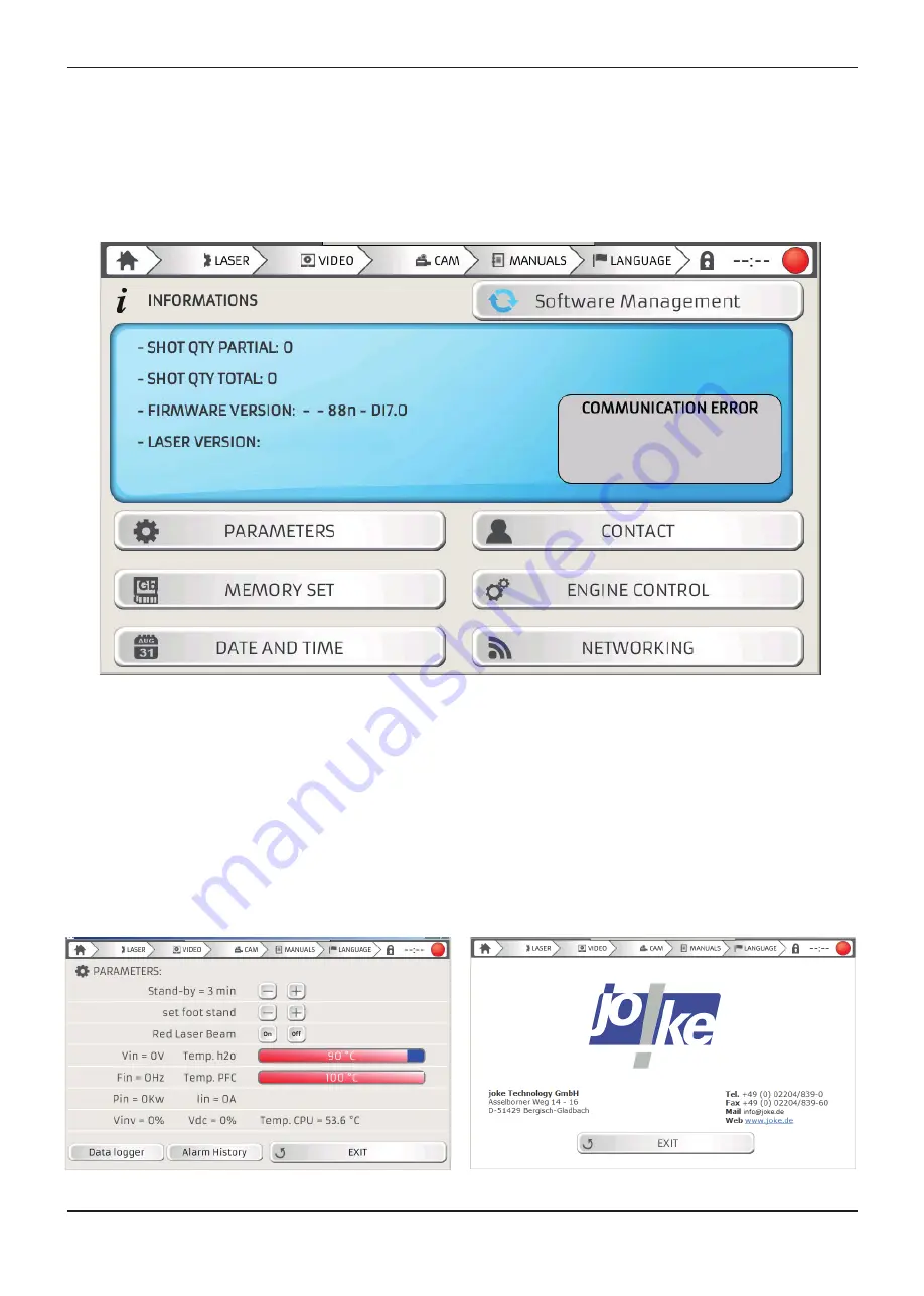
Figure 28 – Information menu screen
INFO SCREEN
Press the INFO button to access the information menu, which contains 6 setting options (Figure 28).
• PARAMETER –
which may be used to set-up different parameters and view data relating to the
machine status, as shown in figure 29. It is possible to select machine stand-by mode, switch the
pointers on or off and access the alarm history and the data logger using the two buttons at the bottom
left of the screen.
Figure 29 – Parameters screen
Figure 30 – Contact screen
Содержание 4910880
Страница 1: ......
Страница 4: ......
Страница 6: ...SAFETY ...
Страница 18: ...INTRODUCTION ...
Страница 24: ...INSTALLATION ...
Страница 40: ...SETTING THE MACHINE PARAMETERS ...
Страница 44: ...WELDING WITH THE ENESKAlaser 1500 mobile ...
Страница 48: ...TROUBLESHOOTING FAULT MAINTENANCE ...
Страница 60: ...GENERAL SAFETY REQUIREMENTS DURING WELDING ...
Страница 65: ...NOTE ...
Страница 66: ...NOTE ...
Страница 67: ...NOTE ...


