Dehydration
To make sure that there is confidence in the vacuum decay related to moisture boiling off,
only perform the dehydration process after the system has been thoroughly leak checked. The
dehydration process is only needed if the following occurs:
1. The nitrogen holding charge on shipments other than Form 1 has been lost.
2. The system has been open to the atmosphere for any length of time.
3. Tube leaks have introduced moisture to the refrigerant circuit.
4. Indications of moisture contamination have appeared in any of the sight glasses
Dehydration of a refrigerant system can be obtained by the evacuation method because the water
present in the system reacts much as a refrigerant would. However, the vacuum pressure in the
system cannot always be pulled down to a point where its saturation temperature is considerably
below that of the equipment room temperature due to low ambient room conditions and other
factors. As a result, you might need to use an external heat source or flow warm water through
at least one vessel to raise the vessel internal temperature. This ensures that heat flows into the
system and helps to vaporize the water, so that a large percentage of it can be removed by the
vacuum pump.
The length of time necessary for the dehydration of a system depends on the size or volume of the
system, the temperature of the vessels, the capacity and efficiency of the vacuum pump, the room
temperature, and the quantity of water present in the system. You can use an external heat source
to shorten the dehydration time, as discussed in the previous paragraph. If you use a vacuum
gauge as suggested, the corresponding saturation temperature can be used as a reference. If the
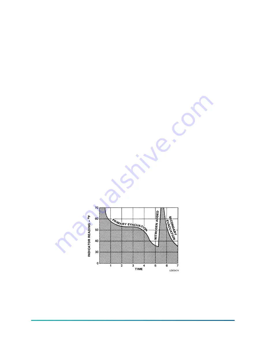
system has been pressure tested and found to be tight before evacuation, then the saturation
temperature recordings should follow a curve similar to the typical saturation curve in Figure 53.
The temperature of any trapped water in the chiller drops as the pressure decreases, until the
boiling point is reached. At this point, the temperature levels off and remains at this level until
all of the water in the shell is vaporized. When this final vaporization has occurred, the pressure
and temperature continue to drop until eventually a temperature of 35°F (1.6°C) or a pressure of
5,000 μm is reached. Because vacuum pumps have the capacity to overcome the boiling rate of the
trapped moisture, do not go below this pressure at this point.
Figure 53: Saturation curve
When this point is reached, practically all of the air has been evacuated from the system, but a small
amount of moisture still remains. In order to provide a medium for carrying this residual moisture
to the vacuum pump, nitrogen must be introduced into the system to bring it to atmospheric
pressure and the indicator temperature will return to approximately ambient temperature. Close
off the system again, and start the second evacuation. The relatively small amount of moisture left
YVAM Control Center
130
Содержание YORK YVAM 0350
Страница 2: ...2 YVAM Control Center...
Страница 10: ...Figure 4 Variable speed drive nomenclature YVAM Control Center 10...
Страница 15: ...Figure 8 System piping and instrumentation diagram P ID 15 YVAM Control Center...
Страница 118: ...Figure 47 Drive logic board Callout Component Callout Component A U35 B U38 C U37 D U36 YVAM Control Center 118...
Страница 154: ...Figure 62 Sample printout status or history YVAM Control Center 154...
Страница 155: ...Figure 63 Sample printout status or history continued 155 YVAM Control Center...
Страница 156: ...Figure 64 Sample printout setpoints YVAM Control Center 156...
Страница 157: ...Figure 65 Sample printout setpoints continued 157 YVAM Control Center...
Страница 158: ...Figure 66 Sample printout schedule YVAM Control Center 158...
Страница 159: ...Figure 67 Sample printout sales order 159 YVAM Control Center...
Страница 160: ...Figure 68 Sample printout security log report YVAM Control Center 160...


