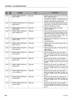
SECTION 5 - JLG CONTROL SYSTEM
5-46
31215923
443
4
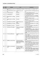
4 "LSS Battery Voltage High"
No Response.
• The LSS Supply Voltage is Greater than 34V.
• Check battery supply and wiring to the LSS Control Module.
444
4
4 “LSS Battery Voltage Low”
No Response.
• The LSS Supply Voltage is Less than 9V.
• Check battery supply and wiring to the LSS Control Module.
4463
4
4 "Rear Left Module - Voltage Out Of Range" Lift Up, Drive and Leveling Jack Func-
tions Prevented.
• UGM is detecting that the Left Power Controller's Voltage is
greater than 65V or less than 12V.
• Check the wiring at the CO371-J1 connector pin 10 for dam-
age. If the wiring is okay, then check Fuse F3 in the Fuse
Block. If the fuse is okay, then check the Power PWR Relay
RL375. If Relay is okay, then check 48V IGN buss MS416 and
IGN PWR Relay RL373 that they are functioning properly.
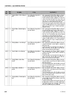
4464
4
4 "Rear Right Module - Voltage Out Of
Range"
Lift Up, Drive and Leveling Jack Func-
tions Prevented.
• UGM is detecting that the Right Power Controller's Voltage is
greater than 65V or less than 12V.
• Check the wiring at the CO342-J1 connector pin 10 for dam-
age. If the wiring is okay, then check Fuse F2 in the Fuse
Block. If the fuse is okay, then check the Power PWR Relay
RL375. If Relay is okay, then check 48V IGN buss MS416 and
IGN PWR Relay RL373 that they are functioning properly.
4467
4
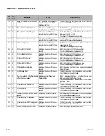
4 "Control Voltage Too High - System Shut-
down"
All Machine Functions are Pre-
vented.
• UGM detects the Machine's Control System Voltage is higher
than 16V.
• Check Voltage Output of Machine's DC/DC Convertor.
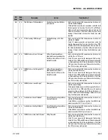
4468
4
4 "Control Voltage Low"
No Response.
• UGM detects the Machine's Control System Voltage is less
than 11V.
• Check Voltage Output of Machine's DC/DC Convertor.
4481
4
4 "System DC Current - At Maximum"
Drive Speed Restricted to Elevated
Speed.
• UGM is detecting that the Power Module is communicating
that Current Output (both modules combined) is higher than
450A.
4482
4
4 "Wheel Drive Components - Too Cold"
Drive Speed Restricted to Elevated
Speed.
• UGM is detecting the Power Modules are communicating
that the Drive Motor Temperatures are less than -18C
degrees.
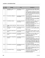
4692
4
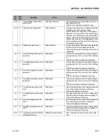
6 "Rear Left Brake - Short To Ground Or Open
Circuit"
Drive, Lift Up and Leveling Jack Func-
tions are Prevented.
• UGM is detecting that the Left Power Module is communi-
cating the brake has a short to 48V B-.
• Check pins 7 and 8 of connector X425A for short to B-. Check
pins 2 and 4 of connector CO371-J1 for a short to B-. Check
pins 7 and 8 of the connector at the left rear drive motor for a
short to B-.
4693
4
6 "Rear Right Brake - Short To Ground Or
Open Circuit"
Drive, Lift Up and Leveling Jack Func-
tions are Prevented.
• UGM is detecting that the Right Power Module is communi-
cating the brake has a short to 48V B-.
• Check pins 7 and 8 of connector X424A for short to B-. Check
pins 2 and 4 of connector CO342-J1 for a short to B-. Check
pins 7 and 8 of the connector at the right rear drive motor for
a short to B-.
4696
4
6 "Rear Right Module - Rear Right Brake
Driver Permanently Off"
Drive, Lift Up and Leveling Jack Func-
tions are Prevented.
• UGM is detecting that the Right Power Module is communi-
cating an internal error with the Electric Brake Driver.
• The Power Module will need replaced.
4697
4
6 "Rear Left Module - Rear Left Brake Driver
Permanently Off"
Drive, Lift Up and Leveling Jack Func-
tions are Prevented.
• UGM is detecting that the Left Power Module is communi-
cating an internal error with the Electric Brake Driver.
• The Power Module will need replaced.
DTC
Code
Flash
Code
Description
Action
Item Check List
Содержание ERT2669
Страница 2: ......
Страница 4: ...INTRODUCTION A 2 31215923 REVISON LOG Original Issue A January 08 2021...
Страница 12: ...viii 31215923 TABLE OF CONTENTS...
Страница 40: ...SECTION 1 SPECIFICATIONS 1 22 31215923...
Страница 58: ...SECTION 2 GENERAL 2 18 31215923...
Страница 187: ...SECTION 4 BASIC HYDRAULIC INFORMATION SCHEMATICS 31215923 4 11...
Страница 206: ...SECTION 4 BASIC HYDRAULIC INFORMATION SCHEMATICS 4 30 31215923...
Страница 221: ...SECTION 4 BASIC HYDRAULIC INFORMATION SCHEMATICS 31215923 4 45 Figure 4 33 Lift Cylinder MAF46290...
Страница 223: ...SECTION 4 BASIC HYDRAULIC INFORMATION SCHEMATICS 31215923 4 47 Figure 4 35 Leveling Jack Cylinder MAF46280...
Страница 225: ...SECTION 4 BASIC HYDRAULIC INFORMATION SCHEMATICS 31215923 4 49...
Страница 242: ...SECTION 4 BASIC HYDRAULIC INFORMATION SCHEMATICS 4 66 31215923...
Страница 307: ...SECTION 5 JLG CONTROL SYSTEM 31215923 5 65...
Страница 334: ...SECTION 6 LSS SETUP CALIBRATION SERVICE 6 12 31215923...
Страница 362: ...SECTION 7 GENERAL ELECTRICAL INFORMATION SCHEMATICS 7 28 31215923...
Страница 374: ...SECTION 7 GENERAL ELECTRICAL INFORMATION SCHEMATICS 7 40 31215923...
Страница 375: ......

