SECTION 4 - BASIC HYDRAULIC INFORMATION & SCHEMATICS
4-4
31215923
4.5
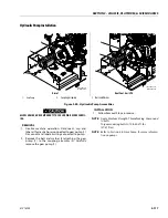
GEAR PUMP PRIMING
The gear pump is mounted with the suction hose up. Air
trapped in this area can cause an air lock on start up.
during this period, the pump is running dry, which can
cause gear wear, which affects the volumetric efficiency
of the pump.
1. Fill the hydraulic tank to the full mark.
2. Using a 3/4 in. wrench, loosen the pressure hose
small section of the gear pump (steering section).
The hose fitting does not need to be removed, just
loosened enough to let the air escape.
3. When oil leaks at the hose end, re-torque the hose
end to 115 ft. lbs. (155 Nm). The pump is primed and
the pumps are ready to start.
4.6
HYDRAULIC COMPONENT START-UP
PROCEDURES & RECOMMENDATIONS
From a hydrostatic component standpoint, the goal at
system start up is to put into functional operation, the
hydrostatic system in such a way as to preserve the
designed life span of the system. The following start-up
procedure should be adhered to whenever a new pump
or motor is initially installed into a machine, or a system
is restarted after either a pump or motor has been
removed and/or replaced.
THE FOLLOWING PROCEDURE MAY REQUIRE THE MACHINE TO BE DIS-
ABLED (WHEELS RAISED OFF THE GROUND, WORK FUNCTIONS DIS-
CONNECTED, ETC.) WHILE PERFORMING THE PROCEDURE IN ORDER
TO PREVENT INJURY. TAKE NECESSARY SAFETY PRECAUTIONS BEFORE
MOVING THE VEHICLE/MACHINE.
Prior to installing the pump and/or motor, inspect the
unit(s) for damage that may have been incurred during
shipping and handling. Ensure all system components
(reservoir, hoses, valves, fittings, heat exchanger, etc.)
are clean prior to filling with fluid.
Fill the reservoir with recommended hydraulic fluid. This
fluid should be passed through a 10 micron (nominal,
no bypass) filter prior to entering the reservoir. The use
of contaminated fluid will cause damage to the compo-
nents, which may result in unexpected vehicle/machine
movement.
NOTE:
If a pump or motor is being replaced due to internal
damage, the remaining units (pump or motors) need
to be inspected for damage and contamination, and
the entire hydraulic system will need to be flushed
and the fluid replaced. Failure to do so may cause
considerable damage to the entire system.
The inlet line leading from the reservoir to the pump
must be filled prior to start-up. Check the inlet line for
property tightened fittings and make sure it is free of
restrictions and air leaks.
NOTE:
In most cases, the reservoir is above the pump inlet
so that the pressure head created by the higher oil
level helps to keep the inlet pressures within an
acceptable range and prevent high vacuum levels.
However, due to hose routing or low reservoir loca-
tions, there may be air trapped within this line. It is
important to ensure that the air is bled from this line.
This can be accomplished by loosening the hose at
the fitting closest to the pump. When oil begins to
flow, the line is full, the air has been purged, and the
fitting can be re-tightened to its specified torque. If
the tank needs to be pressurized in order to start the
flow of oil, a vacuum reading should be taken at the
inlet of the pump during operation in order to verify
Содержание ERT2669
Страница 2: ......
Страница 4: ...INTRODUCTION A 2 31215923 REVISON LOG Original Issue A January 08 2021...
Страница 12: ...viii 31215923 TABLE OF CONTENTS...
Страница 40: ...SECTION 1 SPECIFICATIONS 1 22 31215923...
Страница 58: ...SECTION 2 GENERAL 2 18 31215923...
Страница 187: ...SECTION 4 BASIC HYDRAULIC INFORMATION SCHEMATICS 31215923 4 11...
Страница 206: ...SECTION 4 BASIC HYDRAULIC INFORMATION SCHEMATICS 4 30 31215923...
Страница 221: ...SECTION 4 BASIC HYDRAULIC INFORMATION SCHEMATICS 31215923 4 45 Figure 4 33 Lift Cylinder MAF46290...
Страница 223: ...SECTION 4 BASIC HYDRAULIC INFORMATION SCHEMATICS 31215923 4 47 Figure 4 35 Leveling Jack Cylinder MAF46280...
Страница 225: ...SECTION 4 BASIC HYDRAULIC INFORMATION SCHEMATICS 31215923 4 49...
Страница 242: ...SECTION 4 BASIC HYDRAULIC INFORMATION SCHEMATICS 4 66 31215923...
Страница 307: ...SECTION 5 JLG CONTROL SYSTEM 31215923 5 65...
Страница 334: ...SECTION 6 LSS SETUP CALIBRATION SERVICE 6 12 31215923...
Страница 362: ...SECTION 7 GENERAL ELECTRICAL INFORMATION SCHEMATICS 7 28 31215923...
Страница 374: ...SECTION 7 GENERAL ELECTRICAL INFORMATION SCHEMATICS 7 40 31215923...
Страница 375: ......

