SECTION 4 - BASIC HYDRAULIC INFORMATION & SCHEMATICS
4-32
31215923
c. Pressure Setting Adjustment
1. If you are not already in Main Relief Pressure
calibration mode ("SERVICE” Menu, “SET MAIN
RELIEF?" in analyzer access level 1, then follow
steps of Section b., Pressure Setting Check:
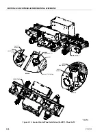
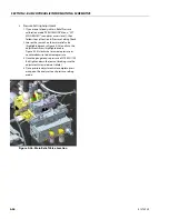
2. Loosen the jam nut on the main relief valve
(highlighted green in Figure 4-20.) and turn the
adjustment screw (highlighted red in
Figure 4-20.) clockwise to increase pressure or
counterclockwise to decrease pressure.
3. Once the gauge reads a pressure of 3990PSI
(275Bar) tighten down the jam nut (making sure
the adjustment screw does not rotate).
4. Once pressure adjustments are complete press
escape on the analyzer to exit pressure setting
mode.
2. Lift Relief Valve;
a. Instrumentation/Setup:
1. Install a pressure gauge, 3000 PSI or higher, at the
M port on the main control valve located in the
hydraulic compartment on the right-hand side of
the machine (see Figure 4-19.).
2. The platform should be in fully elevated position
from the ground control panel position.
NOTE:
Ensure no obstacles are overhead and wind speeds
are below the max allowable before raising the plat-
form. See operator's manual for more details on safe
operating procedures.
b. Pressure Setting Check
1. Start the machine and select command "lift up"
for platform in the fully elevated position.
2. Note the pressure on the gauge connected to the
M port while continuing to command "lift up".
3. If the pressure gauge reads more than 50 PSI
above or below 3100 PSI (213.8 Bar) adjustment
is required (follow the procedure below).
c. Pressure Setting Adjustment
1. Loosen the jam nut on the lift relief valve
(highlighted green in Figure 4-21.) and turn the
adjustment screw (highlighted red in
Figure 4-21.) clockwise to increase pressure or
counterclockwise to decrease pressure.
2. Once the gauge reads a pressure of 3100 PSI
(213.8 Bar) tighten down the jam nut (making
sure the adjustment screw does not rotate)
NOTE:
This will result in ~2750 PSI or 190 Bar at the cylinder
port
Figure 4-20. Main Relief Valve Location
Figure 4-21. Lift Relief Valve
Содержание ERT2669
Страница 2: ......
Страница 4: ...INTRODUCTION A 2 31215923 REVISON LOG Original Issue A January 08 2021...
Страница 12: ...viii 31215923 TABLE OF CONTENTS...
Страница 40: ...SECTION 1 SPECIFICATIONS 1 22 31215923...
Страница 58: ...SECTION 2 GENERAL 2 18 31215923...
Страница 187: ...SECTION 4 BASIC HYDRAULIC INFORMATION SCHEMATICS 31215923 4 11...
Страница 206: ...SECTION 4 BASIC HYDRAULIC INFORMATION SCHEMATICS 4 30 31215923...
Страница 221: ...SECTION 4 BASIC HYDRAULIC INFORMATION SCHEMATICS 31215923 4 45 Figure 4 33 Lift Cylinder MAF46290...
Страница 223: ...SECTION 4 BASIC HYDRAULIC INFORMATION SCHEMATICS 31215923 4 47 Figure 4 35 Leveling Jack Cylinder MAF46280...
Страница 225: ...SECTION 4 BASIC HYDRAULIC INFORMATION SCHEMATICS 31215923 4 49...
Страница 242: ...SECTION 4 BASIC HYDRAULIC INFORMATION SCHEMATICS 4 66 31215923...
Страница 307: ...SECTION 5 JLG CONTROL SYSTEM 31215923 5 65...
Страница 334: ...SECTION 6 LSS SETUP CALIBRATION SERVICE 6 12 31215923...
Страница 362: ...SECTION 7 GENERAL ELECTRICAL INFORMATION SCHEMATICS 7 28 31215923...
Страница 374: ...SECTION 7 GENERAL ELECTRICAL INFORMATION SCHEMATICS 7 40 31215923...
Страница 375: ......


