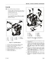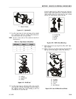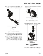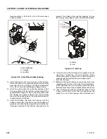
SECTION 3 - CHASSIS, PLATFORM, & SCISSOR ARMS
3-50
31215923
retaining ring (7) into the groove in the cylinder
block.
4. Turn the block over and install the retaining ring (8),
hold-down pins (9), and ball guide (10) to the cylin-
der block.
5. Install the pistons (11) to the slipper retainer (12).
Install the piston/retainer assembly into the cylinder
block. Ensure the concave surface of the retainer
seats on the ball guide. If you're reusing the pistons,
install them to the original block bores. Lubricate the
pistons, slippers, retainer, and ball guide before
assembly. Set the cylinder kit aside on a clean surface
until needed.
6. Install the journal bearings (13) into the housing
seats. Use assembly grease to keep the bearings
seated during assembly. Ensure the locating nubs
drop into the cavities in the seats. If you're reusing
the bearings, install them in the original location and
orientation. Lubricate the journal bearings.
7. Install the swashplate (14) into the housing. Tilt the
swashplate and guide the servo lever ball into its
socket in the servo piston rod. Ensure the swashplate
seats into the journal bearings and moves freely.
Lubricate the running surface of the swashplate.
7
6
5
4
8
9
10
12
11
4. Block Spring Washer
5. Block Spring
6. Outer Washer
7. Spiral Retaining Ring
8. Retaining Ring
9. Holddown Pins
10. Ball Guide
11. Piston
12. Slipper Retainer
Figure 3-27. Cylinder Kit Assembly
14
13
13
13. Journal Bearings
14. Swash Plate
Figure 3-28. Swash Plate and Journal Bearing
Содержание ERT2669
Страница 2: ......
Страница 4: ...INTRODUCTION A 2 31215923 REVISON LOG Original Issue A January 08 2021...
Страница 12: ...viii 31215923 TABLE OF CONTENTS...
Страница 40: ...SECTION 1 SPECIFICATIONS 1 22 31215923...
Страница 58: ...SECTION 2 GENERAL 2 18 31215923...
Страница 187: ...SECTION 4 BASIC HYDRAULIC INFORMATION SCHEMATICS 31215923 4 11...
Страница 206: ...SECTION 4 BASIC HYDRAULIC INFORMATION SCHEMATICS 4 30 31215923...
Страница 221: ...SECTION 4 BASIC HYDRAULIC INFORMATION SCHEMATICS 31215923 4 45 Figure 4 33 Lift Cylinder MAF46290...
Страница 223: ...SECTION 4 BASIC HYDRAULIC INFORMATION SCHEMATICS 31215923 4 47 Figure 4 35 Leveling Jack Cylinder MAF46280...
Страница 225: ...SECTION 4 BASIC HYDRAULIC INFORMATION SCHEMATICS 31215923 4 49...
Страница 242: ...SECTION 4 BASIC HYDRAULIC INFORMATION SCHEMATICS 4 66 31215923...
Страница 307: ...SECTION 5 JLG CONTROL SYSTEM 31215923 5 65...
Страница 334: ...SECTION 6 LSS SETUP CALIBRATION SERVICE 6 12 31215923...
Страница 362: ...SECTION 7 GENERAL ELECTRICAL INFORMATION SCHEMATICS 7 28 31215923...
Страница 374: ...SECTION 7 GENERAL ELECTRICAL INFORMATION SCHEMATICS 7 40 31215923...
Страница 375: ......


