SECTION 3 - CHASSIS, PLATFORM, & SCISSOR ARMS
3-94
31215923
E-0-6-2
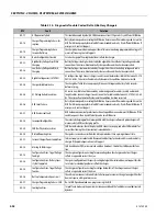
CAN Battery Voltage Report Mis-
match
The charger compares the Battery written voltage with its output voltage. Check that the cor-
rect voltage is being sent to the charger. Check that the output cable resistance matches the
charger setting. Check for other sources of voltage drop.
E-0-6-3
Stackable Charging - Incompatible
Secondary Charger(s)
Query the master to identify which secondary has the bad configuration or interface version.
E-0-6-4
J1939 Address - Charger Failed to
Claim
The most likely cause of this problem is that two or more chargers, configured for the same fixed
address, have been connected to the same bus in error. Alternatively there could be a configura-
tion issue and the addresses available to the charger are already being used by other customer
devices on the bus.
E-0-6-5
J1939 Address - Other Device Failed
to Claim
Read SPN 611 from the charger(s) that has raised this alarm. This will contain the 64-bit J1939
"Name" of the device that could not claim its address.
If this device is another Delta-Q charger (manufacturer code 800, function Id 141) and this is a
stackable charging system then possible causes include:
i) Incorrectly configured chargers
ii) Address conflicts exist between the charger and other devices on the bus
iii) Master/Secondary wiring fault.
The alarm will be cleared on charger reset - but may immediately trigger if the address conflict
persists.
E-0-6-6
Battery Voltage Higher Than Config-
ured Maximum
Check if the charger is connected to the right battery, or the maximum voltage configured is too
low.
E-0-6-7
CAN Physical Layer Error - Before
Messages Received
CANbus network error. Check the physical CAN connector, electrical bus conditions and other
CAN modules for correct functioning. For example check termination resistance is approx
60ohms.
E-0-6-8
Missing CAN Messages While Not
Charging
Monitored messages (Heartbeat, PGN, PDO) lost while charger output off. Check the networked
CANbus device(s) for correct function and messages.
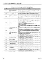
F-0-0-1
DC-DC Circuit Excessive Leakage
Internal charger fault. Remove AC and battery for minimum 30 seconds and retry charger. If it
fails again, do not continue to use the charger - replace the unit.
F-0-0-2
PFC Circuit Excessive Leakage
Internal charger fault. Remove AC and battery for minimum 30 seconds and retry charger. If it
fails again, do not continue to use the charger - replace the unit.
F-0-0-3
PFC Circuit Boost Failure
Internal charger fault. Remove AC and battery for minimum 30 seconds and retry charger. If it
fails again, do not continue to use the charger - replace the unit.
F-0-0-4
Battery Current Sense Circuit Failure
Internal charger fault. Remove AC and battery for minimum 30 seconds and retry charger. If it
fails again, do not continue to use the charger - replace the unit.
F-0-0-5
DC Relay Circuit - Rationality
Internal charger fault. Remove AC and battery for minimum 30 seconds and retry charger. If it
fails again, do not continue to use the charger - replace the unit.
F-0-0-6
Battery Current Sense Circuit Ratio-
nality
Internal charger fault. Remove AC and battery for minimum 30 seconds and retry charger. If it
fails again, do not continue to use the charger - replace the unit.
F-0-0-7
DC-DC Circuit Failure
Internal charger fault. Remove AC and battery for minimum 30 seconds and retry charger. If it
fails again, do not continue to use the charger - replace the unit.
F-0-0-9
Internal Software Exception
Internal charger fault. Remove AC and battery for minimum 30 seconds and retry charger. If it
fails again, do not continue to use the charger - replace the unit.
F-0-1-0
Fault on Connected Charger
Stackable and VCIM systems: Check connected chargers individually for faults.
Table 3-15. Diagnostic Trouble Codes (Delta Q Battery Charger)
DTC
Fault
Solution
Содержание ERT2669
Страница 2: ......
Страница 4: ...INTRODUCTION A 2 31215923 REVISON LOG Original Issue A January 08 2021...
Страница 12: ...viii 31215923 TABLE OF CONTENTS...
Страница 40: ...SECTION 1 SPECIFICATIONS 1 22 31215923...
Страница 58: ...SECTION 2 GENERAL 2 18 31215923...
Страница 187: ...SECTION 4 BASIC HYDRAULIC INFORMATION SCHEMATICS 31215923 4 11...
Страница 206: ...SECTION 4 BASIC HYDRAULIC INFORMATION SCHEMATICS 4 30 31215923...
Страница 221: ...SECTION 4 BASIC HYDRAULIC INFORMATION SCHEMATICS 31215923 4 45 Figure 4 33 Lift Cylinder MAF46290...
Страница 223: ...SECTION 4 BASIC HYDRAULIC INFORMATION SCHEMATICS 31215923 4 47 Figure 4 35 Leveling Jack Cylinder MAF46280...
Страница 225: ...SECTION 4 BASIC HYDRAULIC INFORMATION SCHEMATICS 31215923 4 49...
Страница 242: ...SECTION 4 BASIC HYDRAULIC INFORMATION SCHEMATICS 4 66 31215923...
Страница 307: ...SECTION 5 JLG CONTROL SYSTEM 31215923 5 65...
Страница 334: ...SECTION 6 LSS SETUP CALIBRATION SERVICE 6 12 31215923...
Страница 362: ...SECTION 7 GENERAL ELECTRICAL INFORMATION SCHEMATICS 7 28 31215923...
Страница 374: ...SECTION 7 GENERAL ELECTRICAL INFORMATION SCHEMATICS 7 40 31215923...
Страница 375: ......


