SECTION 5 - JLG CONTROL SYSTEM
5-38
31215923
2512
2
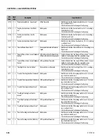
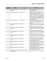
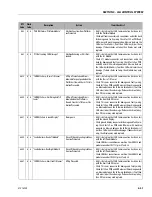
5 “Elev Angle Sensor Not Detecting
Change”
Lift Up Prevented.
• The Arm Angle Sensor Value is not Changing while a Lift Up
Function is being Commanded.
• Check the Arm stack Tilt Sensor for damage or faulty wiring.
Check the Lift Enable and Flow Control Valves for damage or
faulty wiring.
252
2
5 “Elev Angle Sensors Have Not Been Cali-
brated”
Lift Up Prevented.
• The Elevation Angle Sensor Calibration has not been per-
formed.
253
2
5 “Drive Prevented - Charger Connected”
Drive functionality Prevented.
• UGM is detecting that the Battery Charger is Plugged in.
2538
2
5 “Functions Prevented - Charger Con-
nected”
All Machine Functions Prevented.
• UGM is detecting that the Battery Charger is Plugged in.
2555
2
5 “Function Prevented - Selected Before
FSW”
Functions Prevented until the Joy-
stick is Centered.
• If the Market = Korea, the Joystick is out of the Center Posi-
tion before the Footswitch is pressed.
2564
2
5 “Drive Prevented - Left Brake Not Releas-
ing”
Drive functionality Prevented.
• Power Module is communicating to UGM that the Left Brake
is Not Releasing.
• Check connector connections between Left Power Module
and Drive Motor for damage and faulty wiring.
2565
2
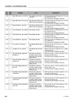
5 “Drive Prevented - Right Brake Not
Releasing”
Drive functionality Prevented.
• Power Module is communicating to UGM that the Right
Brake is Not Releasing.
• Check connector connections between Left Power Module
and Drive Motor for damage and faulty wiring.
2588
2
5 “Function Prevented - Leveling Jacks
State Unknown”
Drive and Lift Up Prevented.
• The UGM has determined that One/All of the Leveling Jack
Stow Switches are not reading stowed and Pressure Trans-
ducers are reading that the Leveling Jacks are not Extended.
• Check if a Leveling Jack cylinder has leaked down out of
stowed position, attempt Leveling Jack Retract. Check the
Platform Display or Analyzer Diagnostics to identify which
jack is showing as Open and check that switch for damage or
faulty wiring.
2593
2
5 “Function Problem - Speed Select Perma-
nently Selected”
If Machine is in Platform Mode, All
Machine Functions are Prevented.
• The Platform Drive Speed Select Digital Input Signal at the
Platform Module (Pin 20) is HIGH at Machine Power On
• Check the select switch for damage or faulty wiring.
3111
3
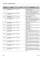
1 "Main Contactor Driver - Permanently Off” Lift Up, Drive and Leveling Jacks are
Prevented.
• UGM has detected the Power Module is communicating Con-
tactor Driver Fault.
• The Right Power Controller will need replaced.
3112
3
1 “Main Contactor - Open Circuit”
Lift Up, Drive and Leveling Jacks are
Prevented.
• UGM is detecting that the Power Module is communicating a
Contactor Fault.
• Check the Main Contactor wiring at RL371 connector. If wir-
ing is okay, check contactor functionality and confirm Con-
tactor Contacts are closing, it may need replaced. If contactor
is okay, then the Right Power Controller will need replaced.
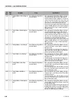
3117
3
1 “Main Contactor Coil - Open Circuit”
Lift Up, Drive and Leveling Jacks are
Prevented.
• UGM is detecting that the Power Module is communicating a
Contactor Fault.
• Check the Main Contactor wiring at RL371 connector. If wir-
ing is okay, check contactor functionality, it may need
replaced. If contactor is okay, then the Right Power Control-
ler will need replaced.
DTC
Code
Flash
Code
Description
Action
Item Check List
Содержание ERT2669
Страница 2: ......
Страница 4: ...INTRODUCTION A 2 31215923 REVISON LOG Original Issue A January 08 2021...
Страница 12: ...viii 31215923 TABLE OF CONTENTS...
Страница 40: ...SECTION 1 SPECIFICATIONS 1 22 31215923...
Страница 58: ...SECTION 2 GENERAL 2 18 31215923...
Страница 187: ...SECTION 4 BASIC HYDRAULIC INFORMATION SCHEMATICS 31215923 4 11...
Страница 206: ...SECTION 4 BASIC HYDRAULIC INFORMATION SCHEMATICS 4 30 31215923...
Страница 221: ...SECTION 4 BASIC HYDRAULIC INFORMATION SCHEMATICS 31215923 4 45 Figure 4 33 Lift Cylinder MAF46290...
Страница 223: ...SECTION 4 BASIC HYDRAULIC INFORMATION SCHEMATICS 31215923 4 47 Figure 4 35 Leveling Jack Cylinder MAF46280...
Страница 225: ...SECTION 4 BASIC HYDRAULIC INFORMATION SCHEMATICS 31215923 4 49...
Страница 242: ...SECTION 4 BASIC HYDRAULIC INFORMATION SCHEMATICS 4 66 31215923...
Страница 307: ...SECTION 5 JLG CONTROL SYSTEM 31215923 5 65...
Страница 334: ...SECTION 6 LSS SETUP CALIBRATION SERVICE 6 12 31215923...
Страница 362: ...SECTION 7 GENERAL ELECTRICAL INFORMATION SCHEMATICS 7 28 31215923...
Страница 374: ...SECTION 7 GENERAL ELECTRICAL INFORMATION SCHEMATICS 7 40 31215923...
Страница 375: ......


