SECTION 8 - DIAGNOSTIC TROUBLE CODES
3121222
– JLG Lift –
8-9
253
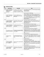
DRIVE PREVENTED -
CHARGER CONNECTED
Driving is not possible while the
vehicle is charging.
•
Check if the charger is connected to off board power source and discon-
nect if desired.
•
Check ANALYZER -> MACHINE SETUP -> CHARGER INTERLOC is set as
desired.
•
Check that charger's red (positive) battery wire connector terminal is
receiving power (24V) from batteries.
•
Check signal from charger interlock connector terminal 2 to ground board
terminal J1-29, where 0VDC indicates charging in process.
254
DRIVE & LIFT UP PRE-
VENTED - CHARGER
CONNECTED
Drive or lift is not possible while
the vehicle is charging AND is
configured to prevent all
motion.
•
Check if the charger is connected to off board power source and discon-
nect if desired.
•
Check ANALYZER -> MACHINE SETUP -> CHARGER INTERLOC is set as
desired. (Must be in ACCESS LEVEL 1 to change.)
•
Check that charger's red (positive) battery wire connector terminal is
receiving power (24V) from batteries.
•
Check signal from charger interlock connector terminal 2 to ground board
terminal J1-29, where 0VDC indicates charging in process.
255
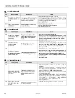
PLATFORM OVER-
LOADED
The load sensing system mea-
sured platform load is excessive.
•
Remove excess weight from the platform.
•
Check that the platform is not caught on something, preventing up or
down movement.
•
If any CAN bus faults are active, troubleshoot those first.
•
Refer to Section 2.3: Troubleshooting in the LSS manual, 3124288.
256
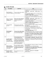
DRIVE PREVENTED -
POTHOLE NOT
ENGAGED
Driving is not possible while ele-
vated since the pot-hole protec-
tion system failed to deploy.
•
Check for obstructions or mechanical problems around the pot-hole pro-
tection mechanisms.
•
Check that the PHP switches are securely mounted.
•
Adjust pot-hole protection switches.
•
Check the pothole protection switches signal and wiring to the ground
board. The left pot-hole protection switch input (24V) is from ground
board terminal J1-9, and its output (24V when deployed) is to ground
board terminal J1-10. The right pot-hole protection switch input (24V) is
from ground board terminal J1-17, and its output (24V when deployed) is
to ground board terminal J1-18.
257
ELEV PROX PERMA-
NENTLY CLOSED -
CHECK PROX AND
ANGLE ADJUSTMENT
The elevation proximity switch
shows the platform to be
stowed, while the elevation
angle sensor shows the platform
to be raised. The elevation prox-
imity switch is only found on cer-
tain older lifts. This switch is not
used on current machines so
this DTC should not occur.
•
Verify that an elevation proximity switch is present on the machine. If
not, ensure ANALYZER -> MACHINE SETUP -> ELEV PROX is set to NOT
INSTALLED. If the switch is present, set ELEV PROX to INSTALLED and check
switch continuity. The switch should close when placed in close proximity
to ferrous metal.
258
DRIVE & LIFT PRE-
VENTED - BRAKES ELEC-
TRICALLY RELEASED
FOR TOWING
Manual brake release mode is
activated with the switch in the
battery box near the ground
control box. Drive or lift is not
possible.
•
Push manual brake release switch again or cycle power to clear manual
brake release mode.
•
Check if the brake release switch is obstructed or jammed.
•
Check the brake release switch signal and wiring to the ground board. The
switch input (24V) is from ground board terminal J1-19, and its output
(24V when closed) is to ground board terminal J1-20.
•
Replace ground board.
259
MODEL CHANGED -
HYDRAULICS SUS-
PENDED - CYCLE EMS
The model selection has been
changed.
•
Check ANALYZER -> MACHINE SETUP -> MODEL NUMBER.
•
Replace ground board.
2-5 Function Prevented
DTC
FAULT MESSAGE
DESCRIPTION
CHECK
Содержание 1230ES
Страница 1: ...AS NZS Service and Maintenance Manual Model s 1230ES P N 3121222 June 22 2017 ...
Страница 2: ...NOTES ...
Страница 24: ...SECTION 1 MACHINE SPECIFICATIONS 1 12 JLG Lift 3121222 NOTES ...
Страница 32: ...SECTION 2 GENERAL SERVICE INFORMATION 2 8 JLG Lift 3121222 NOTES ...
Страница 78: ...SECTION 4 BASE COMPONENTS 4 40 JLG Lift 3121222 NOTES ...
Страница 104: ...SECTION 5 CONTROL COMPONENTS 5 26 JLG Lift 3121222 NOTES ...
Страница 158: ...SECTION 8 DIAGNOSTIC TROUBLE CODES 8 22 JLG Lift 3121222 NOTES ...
Страница 169: ...SECTION 9 GENERAL ELECTRICAL INFORMATION SCHEMATICS 3121222 JLG Lift 9 11 Figure 9 5 Connector Installation ...
Страница 198: ...SECTION 9 GENERAL ELECTRICAL INFORMATION SCHEMATICS 9 40 JLG Lift 3121222 ...
Страница 199: ...SECTION 9 GENERAL ELECTRICAL INFORMATION SCHEMATICS 3121222 JLG Lift 9 41 ...
Страница 200: ...SECTION 9 GENERAL ELECTRICAL INFORMATION SCHEMATICS 9 42 JLG Lift 3121222 ...
Страница 202: ...SECTION 9 GENERAL ELECTRICAL INFORMATION SCHEMATICS 9 44 JLG Lift 3121222 NOTES ...


