


SECTION 4 - BASE COMPONENTS
4-22
– JLG Lift –
3121222
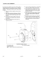
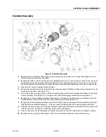
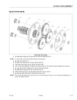
Spindle Sub-Assembly
Spindle Sub-Assembly
1.
Using the appropriate pressing tool (T-207925), press in the 2 Main Bushings (12) in the upper bore of the
Spindle (1). The lower bushing needs to flush with the bottom of the bore and the upper bushing needs to
be flush with the bottom of the bore.
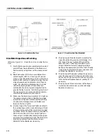
2.
Using the appropriate pressing tool (T-182377), press on Main Bearing (14) until it is fully seated.
3.
Insert the Motor Shaft Bearing (15) into the center bore of the Spindle (1). The bearing is a slight slip fit, but
it may require some press to assemble if the bearing becomes misaligned.
4.
Retain the Motor Shaft Bearing (15) installing Spiral Retaining Ring (28) into groove in Spindle (1).
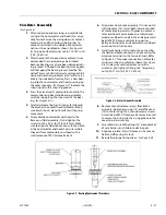
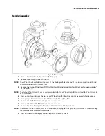
5.
Use the Output Planet Pin (10) as a pressing tool to install the Planet Bushing (26) into the bore of each
Planet Gear (9). The shaft will help guide the bushing into the bore as well as prevent damage from the
press.
6.
Place Tanged Thrust Washer (32) into each planet "window" of the Spindle (1). Make sure the tang sits in the
cast groove on the inside of the window.
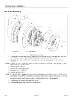
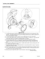
7.
Place a Thrust Washer (25) onto the Output Planet Gear (9). Line up the bores as best as you can. Use grease
to hold the Thrust Washer in place.
8.
Slide the Output Planet Gear (9) into the window with the Tanged Thrust Washer (32) until the bores line up.
9.
Insert an Output Planet Shaft (10) into the Planet Shaft hole of the Spindle (1) and through the bores of the
Thrust Washers (25) & (32) and the Planet Gear (9).
10.
Before pressing the Output Planet Shaft (10) into the Spindle (1), make sure the gear spins freely.
(continued next page)
Содержание 1230ES
Страница 1: ...AS NZS Service and Maintenance Manual Model s 1230ES P N 3121222 June 22 2017 ...
Страница 2: ...NOTES ...
Страница 24: ...SECTION 1 MACHINE SPECIFICATIONS 1 12 JLG Lift 3121222 NOTES ...
Страница 32: ...SECTION 2 GENERAL SERVICE INFORMATION 2 8 JLG Lift 3121222 NOTES ...
Страница 78: ...SECTION 4 BASE COMPONENTS 4 40 JLG Lift 3121222 NOTES ...
Страница 104: ...SECTION 5 CONTROL COMPONENTS 5 26 JLG Lift 3121222 NOTES ...
Страница 158: ...SECTION 8 DIAGNOSTIC TROUBLE CODES 8 22 JLG Lift 3121222 NOTES ...
Страница 169: ...SECTION 9 GENERAL ELECTRICAL INFORMATION SCHEMATICS 3121222 JLG Lift 9 11 Figure 9 5 Connector Installation ...
Страница 198: ...SECTION 9 GENERAL ELECTRICAL INFORMATION SCHEMATICS 9 40 JLG Lift 3121222 ...
Страница 199: ...SECTION 9 GENERAL ELECTRICAL INFORMATION SCHEMATICS 3121222 JLG Lift 9 41 ...
Страница 200: ...SECTION 9 GENERAL ELECTRICAL INFORMATION SCHEMATICS 9 42 JLG Lift 3121222 ...
Страница 202: ...SECTION 9 GENERAL ELECTRICAL INFORMATION SCHEMATICS 9 44 JLG Lift 3121222 NOTES ...


