SECTION 5 - CONTROL COMPONENTS
5-8
– JLG Lift –
3121222
5.4
POWER MODULE - P/N-1600346
1230ES Scissors built starting in mid year 2010 replaced the Sev-
con Power Module (P/N-1600473) with the ZAPI Power Module (P/
N-1001092456).
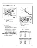
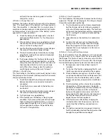
The Sevcon Power Module is located at the front-left side
of the machine inside the compartment as shown in
below. Use the following instructions when remov-
ing and installing the power module.
Removal
1.
Turn off power machine power and disconnect
the batteries.
NOTE:
Note the wire terminal locations when removing the
Power Module (See Figure 5-1.).
2.
Disconnect all wires from the power module and
remove the module mounting bolts, remove
module from the machine.
Installation
1.
Be sure that the terminals are oriented as shown.
2.
After installing the power module, begin con-
necting the wires back to the controller. (Refer-
ence Figure 5-1.)
do not overtighten the terminal bolts, or damage to the unit could
occur.
3.
Torque the terminal bolts to 5 ft lb. (7 Nm).
4.
After all connections to the power module are
made, the battery can be reconnected.
Power Module Electrical Evaluation
Several basic electrical tests can be performed on the
Power Module. Failure of one of these evaluations is signif-
icant and may indicate that the device is physically dam-
aged. If a Power Module is suspected to be faulty,
thoroughly examine the rest of the system for possible
damage.
Make all measurements with a voltmeter set to resistance
scale (Ohms) (Refer to Section 9 - Figure 9-2., Resistance
Measurement). Disconnect the Main Battery Disconnect
and all cables from the Power Module during this analysis.
Wait 60 seconds after power is disconnected to allow
internal charge to dissipate (risk of hazard, improper read-
ings otherwise).
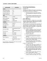
Figure 5-3. Power Module - Installation
1.
Power Module
2.
Mounting Screws
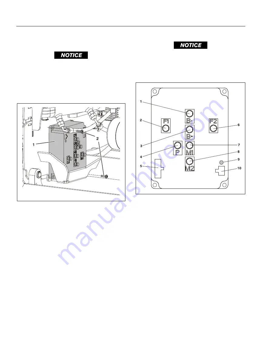
Figure 5-4. Sevcon Power Module Terminals
1.
B – (battery (–) terminal)
2.
F1 (motor field terminal)
3.
B+ (battery (+) terminal)
4.
P - (pump (–) terminal)
5.
Mini-Fit Jr/B-
Connector
6.
F2 - (motor field terminal)
7.
M1 - (motor armature terminal)
8.
M2 - (motor armature terminal)
9.
DTC Flash Code LED Indicator
10.
Unused
Содержание 1230ES
Страница 1: ...AS NZS Service and Maintenance Manual Model s 1230ES P N 3121222 June 22 2017 ...
Страница 2: ...NOTES ...
Страница 24: ...SECTION 1 MACHINE SPECIFICATIONS 1 12 JLG Lift 3121222 NOTES ...
Страница 32: ...SECTION 2 GENERAL SERVICE INFORMATION 2 8 JLG Lift 3121222 NOTES ...
Страница 78: ...SECTION 4 BASE COMPONENTS 4 40 JLG Lift 3121222 NOTES ...
Страница 104: ...SECTION 5 CONTROL COMPONENTS 5 26 JLG Lift 3121222 NOTES ...
Страница 158: ...SECTION 8 DIAGNOSTIC TROUBLE CODES 8 22 JLG Lift 3121222 NOTES ...
Страница 169: ...SECTION 9 GENERAL ELECTRICAL INFORMATION SCHEMATICS 3121222 JLG Lift 9 11 Figure 9 5 Connector Installation ...
Страница 198: ...SECTION 9 GENERAL ELECTRICAL INFORMATION SCHEMATICS 9 40 JLG Lift 3121222 ...
Страница 199: ...SECTION 9 GENERAL ELECTRICAL INFORMATION SCHEMATICS 3121222 JLG Lift 9 41 ...
Страница 200: ...SECTION 9 GENERAL ELECTRICAL INFORMATION SCHEMATICS 9 42 JLG Lift 3121222 ...
Страница 202: ...SECTION 9 GENERAL ELECTRICAL INFORMATION SCHEMATICS 9 44 JLG Lift 3121222 NOTES ...


