


SECTION 8 - DIAGNOSTIC TROUBLE CODES
8-10
– JLG Lift –
3121222
2510
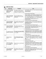
DRIVE PREVENTED -
BRAKES NOT RELEASING
While driving on a level surface,
armature current was > 150A for
five seconds. Brakes assumed to
not be releasing properly.
•
Ensure vehicle is not stuck on something preventing movement.
•
Check / repair drive motor wiring, brakes or mechanical issues.
2511
ELEV ANGLE SENSOR
FAULTY - NOT MOUNTED
The input voltage from the ele-
vation angle sensor indicates
the elevation angle sensor is not
mounted.
•
Check that the elevation angle sensor is securely mounted.
•
Check that the elevation angle sensor mechanisms are intact.
•
Replace elevation angle sensor.
2512
ELEV ANGLE SENSOR
NOT DETECTING
CHANGE
The input voltage from the ele-
vation angle sensor did not
change while vehicle was lifting
up.
•
Check that the elevation angle sensor is securely mounted.
•
Check elevation angle sensor is not jammed or obstructed.
•
If there are any other elevation angle sensor, joystick, or lift up faults,
troubleshoot them before continuing.
•
Replace elevation angle sensor.
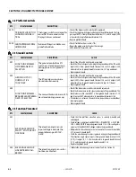
3-1 Line Contactor Open Circuit
DTC
FAULT MESSAGE
DESCRIPTION
CHECK
311
OPEN CIRCUIT LINE
CONTACTOR
The power modules line contac-
tor did not close when ener-
gized. Drive, steer and lift up
prevented.
•
Check contactor main contact wiring to battery (+) terminal and power
controller terminal B+.
•
Contactor solenoid resistance should measure about 52 Ohms.
•
Check contactor solenoid wiring to power module 12 position connector
terminal 8 and ground board terminal J1-19.
•
Check that power module 12 position connector terminal 8 goes from 24V
to near 0V while contactor should be closing. If this happens replace con-
tactor.
•
Replace the line contactor.
312
CONTACTOR DRIVER
PERMANENTLY OFF
The power modules line contac-
tor drive circuitry failed to ener-
gize when requested. Drive,
steer and lift up prevented.
•
Check continuity between contactor connector pin 1 and ground board
socket J1-19.
•
Contactor solenoid resistance should measure about 52 Ohms.
•
Check continuity between contactor connector pin 2 and power module
connector socket 8.
•
Replace power module.
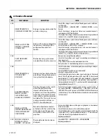
3-2 Line Contactor Short Circuit
DTC
FAULT MESSAGE
DESCRIPTION
CHECK
321
LINE CONTACTOR
MISWIRED ON OR
WELDED
Battery voltage was present at
the power module B+ terminal
at power up. Drive, steer and lift
up prevented.
•
Check wiring of contactor.
•
Check resistance between the studs of the contactor while disconnected
from the machine.
•
Check contactor main contact wiring to battery (+) terminal and power
module terminal B+.
•
Check continuity between contactor connector pin 1 and ground board
socket J1-19.
•
Check continuity between contactor connector pin 2 and power module
12 position connector terminal 8.
•
Measure voltage between power model B+ and B- terminals. If 24V is
present, replace line contactor.
•
Replace power module.
2-5 Function Prevented
DTC
FAULT MESSAGE
DESCRIPTION
CHECK
Содержание 1230ES
Страница 1: ...AS NZS Service and Maintenance Manual Model s 1230ES P N 3121222 June 22 2017 ...
Страница 2: ...NOTES ...
Страница 24: ...SECTION 1 MACHINE SPECIFICATIONS 1 12 JLG Lift 3121222 NOTES ...
Страница 32: ...SECTION 2 GENERAL SERVICE INFORMATION 2 8 JLG Lift 3121222 NOTES ...
Страница 78: ...SECTION 4 BASE COMPONENTS 4 40 JLG Lift 3121222 NOTES ...
Страница 104: ...SECTION 5 CONTROL COMPONENTS 5 26 JLG Lift 3121222 NOTES ...
Страница 158: ...SECTION 8 DIAGNOSTIC TROUBLE CODES 8 22 JLG Lift 3121222 NOTES ...
Страница 169: ...SECTION 9 GENERAL ELECTRICAL INFORMATION SCHEMATICS 3121222 JLG Lift 9 11 Figure 9 5 Connector Installation ...
Страница 198: ...SECTION 9 GENERAL ELECTRICAL INFORMATION SCHEMATICS 9 40 JLG Lift 3121222 ...
Страница 199: ...SECTION 9 GENERAL ELECTRICAL INFORMATION SCHEMATICS 3121222 JLG Lift 9 41 ...
Страница 200: ...SECTION 9 GENERAL ELECTRICAL INFORMATION SCHEMATICS 9 42 JLG Lift 3121222 ...
Страница 202: ...SECTION 9 GENERAL ELECTRICAL INFORMATION SCHEMATICS 9 44 JLG Lift 3121222 NOTES ...


