SECTION 8 - DIAGNOSTIC TROUBLE CODES
3121222
– JLG Lift –
8-15
662
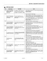
CANBUS FAILURE - PLAT-
FORM MODULE
In platform mode, the control
system failed to receive mes-
sages from the platform board.
•
Turn on machine in ground mode. If DTC 661 is not present check for 24V
between platform box connector terminals D and A. If not 24V, test conti-
nuity from platform box connector socket A to ground board connector
socket J1-6 and test continuity from platform box connector socket D to
ground board connector socket J1-7.
•
If DTC 661 was present in the previous check, disconnect armstack
passthru connector located near the ladder on the left. Turn on in ground
mode. If DTC 661 is not present then there is a problem in armstack har-
ness. Armstack passthru socket 5 to platform box terminal E should have
continuity. Armstack passthru socket 6 to platform box connector termi-
nal F should have continuity. Armstack passthru socket 7 to platform box
connector terminal G should have continuity. Armstack passthru socket 5
to armstack passthru socket 6 resistance should be 120 Ohms +/- 5%.
Armstack passthru socket 5 to armstack passthru socket 7 should measure
open circuit. Armstack passthru socket 6 to armstack passthru socket 7
should measure open circuit.
•
Disconnect armstack passthru and ground board J1. Armstack passthru
pin 5 to ground board socket J1-11 should have continuity. Armstack
passthru pin 6 to ground board socket J1-12 should have continuity. Arm-
stack passthru pin 7 to ground board socket J1-13 should have continuity.
Armstack passthru pin 5 to armstack passthru pin 6 should measure open
circuit. Armstack passthru pin 5 to armstack passthru pin 7 should mea-
sure open circuit. Armstack passthru pin 6 to armstack passthru pin 7
should measure open circuit.
•
Disconnect ground board J1 and power module connector. Ground board
socket J1-31 to power module connector socket 10 should have continu-
ity. Ground board socket J1-32 to power module connector socket 11
should have continuity. Ground board socket J1-31 to J1-32 should mea-
sure open circuit. Ground board socket J1-31 to J1-33 should measure
open circuit. Ground board socket J1-32 to J1-33 should measure open
circuit.
•
Ensure all connections opened above are reconnected. Disconnect power
module connector. Turn on in platform mode. If DTC 662 is no longer pres-
ent replace power module.
•
If DTC 661 and 662 have been present through above steps replace ground
board.
Continued Next Page
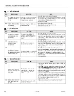
662
(Cont.
)
CANBUS FAILURE - PLAT-
FORM MODULE
(Continued)
In platform mode, the control
system failed to receive mes-
sages from the platform board.
•
Disconnect platform box connector. Open platform box. Disconnect plat-
form board connector. Platform box socket E to platform board J1-3
should have continuity. Platform box socket F to platform board J1-4
should have continuity. Platform box pin E to pin F should measure open
circuit. Platform box pin E to pin G should measure open circuit. Platform
box pin F to pin G should measure open circuit. If these checks are OK
replace platform board.
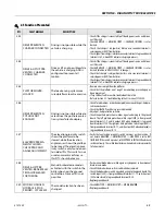
663
CANBUS FAILURE - LOAD
SENSING SYSTEM MOD-
ULE
With load sensing system
enabled, the control system
failed to receive messages from
the load sensing system mod-
ule.
•
Check ANALYZER -> MACHINE SETUP -> MODEL NUMBER is correct.
•
Check ANALYZER -> MACHINE SETUP -> MARKET is correct.
•
Check ANALYZER -> MACHINE SETUP -> LOAD is correct.
•
Check for 24V between load sense system module connector J1-1 and J1-
2.
•
Turn on machine in platform mode. If DTC 662 is present, troubleshoot
that DTC before continuing.
•
Refer to Section 2.3: Troubleshooting in the LSS manual, 3124288.
6-6 Communication
DTC
FAULT MESSAGE
DESCRIPTION
CHECK
Содержание 1230ES
Страница 1: ...AS NZS Service and Maintenance Manual Model s 1230ES P N 3121222 June 22 2017 ...
Страница 2: ...NOTES ...
Страница 24: ...SECTION 1 MACHINE SPECIFICATIONS 1 12 JLG Lift 3121222 NOTES ...
Страница 32: ...SECTION 2 GENERAL SERVICE INFORMATION 2 8 JLG Lift 3121222 NOTES ...
Страница 78: ...SECTION 4 BASE COMPONENTS 4 40 JLG Lift 3121222 NOTES ...
Страница 104: ...SECTION 5 CONTROL COMPONENTS 5 26 JLG Lift 3121222 NOTES ...
Страница 158: ...SECTION 8 DIAGNOSTIC TROUBLE CODES 8 22 JLG Lift 3121222 NOTES ...
Страница 169: ...SECTION 9 GENERAL ELECTRICAL INFORMATION SCHEMATICS 3121222 JLG Lift 9 11 Figure 9 5 Connector Installation ...
Страница 198: ...SECTION 9 GENERAL ELECTRICAL INFORMATION SCHEMATICS 9 40 JLG Lift 3121222 ...
Страница 199: ...SECTION 9 GENERAL ELECTRICAL INFORMATION SCHEMATICS 3121222 JLG Lift 9 41 ...
Страница 200: ...SECTION 9 GENERAL ELECTRICAL INFORMATION SCHEMATICS 9 42 JLG Lift 3121222 ...
Страница 202: ...SECTION 9 GENERAL ELECTRICAL INFORMATION SCHEMATICS 9 44 JLG Lift 3121222 NOTES ...


