


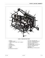

SECTION 5 - CONTROL COMPONENTS
5-4
– JLG Lift –
3121222
5.3
TRACTION SYSTEM
Refer to Section 3.5, TRACTION - Theory of Operation for
more detailed information on Traction System.
Common Traction System Difficulties
1. Ground Module Interlocks
There are a variety of interlocks that prevent
Drive due to system events (Elevated but Pot-
Hole Mechanism Failed to Deploy, etc.). Before
investigating Traction System issues, examine
the JLG Analyzer's HELP Menu while attempting
to Drive from Platform Mode. Refer to the Sec-
tion 5 for explanation of the JLG Analyzer Help
Messages.
2. Power Module Diagnostic Issues
The Power Module executes a self-test during
every power-up to ensure proper functionality. If
a Diagnostic Issue is detected, the Power Module
will not energize the Line Contactor. Instead, it
will flash the Green LED, please refer to Power
Module Diagnostics in Section 5.4, POWER MOD-
ULE - P/N-1600346.
3. Open-Circuit Motor Armature
This issue will allow the vehicle to drive, but one
motor will handle the entire traction load. Motor
overheating and excessive tire wear will result,
along with a lack of traction control.
This situation can be detected by elevating the
vehicle's front wheels and engaging drive (plat-
form stowed). Under DIAGNOSTICS - TRACTION,
the JLG Analyzer's ARM CUR display (Armature
Current Reading) should be less than 50A. One
wheel will rotate at full speed, while the other
will not rotate at all. The Power Module's self-
diagnostics cannot detect this fault unless both
armatures are open-circuit.
To find the source of the difficulty, pull the Main
Battery Disconnect and investigate the wiring
pathways from the Power Controller's M1 and
M2 terminals to the armature on the motor that
does not rotate. Investigate for issues like
improper crimps, loose terminals, and corrosion.
4. Short-Circuit Motor Armature
This issue will allow the vehicle to drive very
slowly or not at all. Rapid motor overheating
(one motor) will result.
This situation can be detected by elevating the
vehicle's front wheels and engaging drive (plat-
form stowed). Under DIAGNOSTICS - TRACTION,
the JLG Analyzer's ARM CUR display (Armature
Current Reading) will hover around 350A. The
FLD CUR display (Field Current Reading) will
hover around 40A. Neither wheel will rotate at
normal speed, but it will be possible to rotate
the drive wheel by hand. The Power Module's
self-diagnostics cannot detect this fault since the
situation appears identical to climbing a steep
grade.
To find the source of the difficulty, pull the Main
Battery Disconnect and disconnect the Arma-
ture Wiring (heavy red and black conductors)
from the suspected drive motor leading to the
Power Module's M1 and M2 Terminals. Re-test
the traction function. If the remaining drive
motor is able to reach full speed (and Armature
Current is less than 50A), the drive motor that
has been disconnected is fault. Investigate for
crushed and burned cables. Note if the drive
motor smells burned.
5. Open-Circuit Motor Field
This issue will allow the vehicle to drive very
slowly or not at all. Rapid motor overheating
(both motors) will result.
This situation can be detected by elevating the
vehicle's front wheels and engaging drive (plat-
form stowed). Under DIAGNOSTICS - TRACTION,
the JLG Analyzer's ARM CUR display (Armature
Current Reading) will hover around 350A. The
FLD CUR display (Field Current Reading) will be
erratic or low (less than 10A). Neither wheel will
rotate at normal speed, but it will be possible to
rotate the drive wheel by hand.
To find the source of the difficulty, pull the Main
Battery Disconnect and disconnect the Field Wir-
ing (two blue wires leading to F1 and F2 Termi-
nals) from the Power Module. Using a voltmeter
set for resistance scale (Ohms), investigate if
there is a short-circuit (less than 5 Ohms)
between the two blue wires (this is normal). If
not, investigate for improper crimps, burned
cables, damaged cables, or damaged field wind-
ings.
6. Short-Circuit Brake Release
This issue will not allow the vehicle to drive.
Rapid motor overheating (both motors) will
result. Continued attempts to drive the vehicle
may result in armature damage.
This situation can be detected by elevating the
vehicle's front wheels and engaging drive (plat-
form stowed). Under DIAGNOSTICS - TRACTION,
the JLG Analyzer's ARM CUR display (Armature
Current Reading) will hover around 350A. The
FLD CUR display (Field Current Reading) will
hover around 40A. Neither wheel will rotate, and
it will be impossible to rotate either drive wheel
by hand. The Ground Module cannot detect this
fault during power-up or self-test since energiz-
ing the brakes could pose a hazard. However, it
may detect this issue during Drive (investigate
using JLG Analyzer).
Содержание 1230ES
Страница 1: ...AS NZS Service and Maintenance Manual Model s 1230ES P N 3121222 June 22 2017 ...
Страница 2: ...NOTES ...
Страница 24: ...SECTION 1 MACHINE SPECIFICATIONS 1 12 JLG Lift 3121222 NOTES ...
Страница 32: ...SECTION 2 GENERAL SERVICE INFORMATION 2 8 JLG Lift 3121222 NOTES ...
Страница 78: ...SECTION 4 BASE COMPONENTS 4 40 JLG Lift 3121222 NOTES ...
Страница 104: ...SECTION 5 CONTROL COMPONENTS 5 26 JLG Lift 3121222 NOTES ...
Страница 158: ...SECTION 8 DIAGNOSTIC TROUBLE CODES 8 22 JLG Lift 3121222 NOTES ...
Страница 169: ...SECTION 9 GENERAL ELECTRICAL INFORMATION SCHEMATICS 3121222 JLG Lift 9 11 Figure 9 5 Connector Installation ...
Страница 198: ...SECTION 9 GENERAL ELECTRICAL INFORMATION SCHEMATICS 9 40 JLG Lift 3121222 ...
Страница 199: ...SECTION 9 GENERAL ELECTRICAL INFORMATION SCHEMATICS 3121222 JLG Lift 9 41 ...
Страница 200: ...SECTION 9 GENERAL ELECTRICAL INFORMATION SCHEMATICS 9 42 JLG Lift 3121222 ...
Страница 202: ...SECTION 9 GENERAL ELECTRICAL INFORMATION SCHEMATICS 9 44 JLG Lift 3121222 NOTES ...


