SECTION 4 - BASE COMPONENTS
3121222
– JLG Lift –
4-15
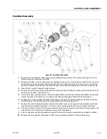
Drive Motor Disassembly
Figure 4-5. Drive Motor Disassembly
1.
Remove the 2 (#8-32UNC x .500in long) screws holding the cover plate (12) in place (See Figure 4-6.) and
remove the cover plate from the motor.
2.
Remove the 2 (M5 x 0.8 x 20mm long) screws holding the cover (15) in place and set aside. These screws are
needed later to manually release the brake. Slide the strain relief bushing (14) and wire harness out of the
cover and remove the cover from the motor. Remove strain relief bushing from wire harness and set aside.
3.
Discard the O-ring (13) located inside the cover.
4.
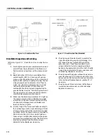
Remove the wire harness (8) from the motor by disconnecting the field connection, brake connection, and
armature connections. (See Figure 4-7.).
5.
Install the 2 cover mounting screws into the threaded holes in the brake assembly and tighten to manually
release the brake. (See Figure 4-7.) or image in the "Manual Disengage Procedure" (See Figure 4-4.).
6.
Remove the 3 screws holding the brake assembly (11) to the motor. Carefully remove the brake assembly
and friction disk (10) from the motor by sliding off of the shaft. (See Figure 4-7.).
7.
Remove the screws holding the commutator end head (9) in place and remove the commutator end head
from the frame and field assembly (1). The armature (2) will be attached to the commutator end head.
8.
Pull back the brush springs (4) in the commutator end head, pull the brush back and rest the springs on the
side of the brush. The brushes should move freely within the holders.
9.
Use an arbor press or a bearing puller to remove the armature from the commutator end head assembly.
10.
Remove the snap ring (6) and bearing (7) from the commutator end head. Discard the bearing.
Содержание 1230ES
Страница 1: ...AS NZS Service and Maintenance Manual Model s 1230ES P N 3121222 June 22 2017 ...
Страница 2: ...NOTES ...
Страница 24: ...SECTION 1 MACHINE SPECIFICATIONS 1 12 JLG Lift 3121222 NOTES ...
Страница 32: ...SECTION 2 GENERAL SERVICE INFORMATION 2 8 JLG Lift 3121222 NOTES ...
Страница 78: ...SECTION 4 BASE COMPONENTS 4 40 JLG Lift 3121222 NOTES ...
Страница 104: ...SECTION 5 CONTROL COMPONENTS 5 26 JLG Lift 3121222 NOTES ...
Страница 158: ...SECTION 8 DIAGNOSTIC TROUBLE CODES 8 22 JLG Lift 3121222 NOTES ...
Страница 169: ...SECTION 9 GENERAL ELECTRICAL INFORMATION SCHEMATICS 3121222 JLG Lift 9 11 Figure 9 5 Connector Installation ...
Страница 198: ...SECTION 9 GENERAL ELECTRICAL INFORMATION SCHEMATICS 9 40 JLG Lift 3121222 ...
Страница 199: ...SECTION 9 GENERAL ELECTRICAL INFORMATION SCHEMATICS 3121222 JLG Lift 9 41 ...
Страница 200: ...SECTION 9 GENERAL ELECTRICAL INFORMATION SCHEMATICS 9 42 JLG Lift 3121222 ...
Страница 202: ...SECTION 9 GENERAL ELECTRICAL INFORMATION SCHEMATICS 9 44 JLG Lift 3121222 NOTES ...


