


SECTION 6 - MAST COMPONENTS
6-4
– JLG Lift –
3121222
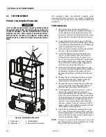
6.6
PLATFORM ASSEMBLY
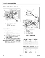
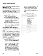
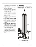
Platform - Extending Mast Unpowered
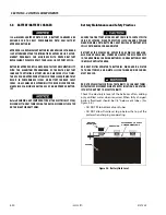
IF LIFT IS DISABLED AND THE MAST CANNOT BE EXTENDED UNDER
THE MACHINE’S OWN POWER, THE PLATFORM MUST BE HOISTED OR
LIFTED BY OTHER MEANS - LIFT PER ILLUSTRATION BELOW - BEFORE
EXTENDING THE MAST, PRESS AND HOLD THE MANUAL DESCENT
VALVE BUTTON ON THE FRONT OF THE MACHINE - WHEN DESIRED
PLATFORM HEIGHT IS REACHED, RELEASE THE MANUAL DESCENT
VALVE.
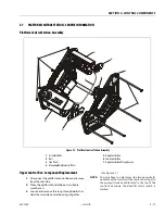
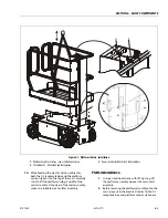
This procedure shows the platform assembly (only)
removal/installation to the mast assembly. The platform
and outer mast section are a one piece manufactured
weldment.
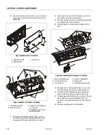
Platform Removal
1.
Extend the mast and raise the platform far
enough out of the base assembly to allow access
to the slide pads on the bottom corners of the
outer mast section, but not to high that you can-
not easily get to the top of the mast to work on
it.
2.
Support platform for later liting, with either an
overhead crane or a fork truck attaching a lifting
strap to remove the platform once the following
steps are completed.
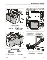
3.
Disconnect machine power at the right side bat-
tery tray using the quick disconnect.
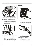
4.
At the four bottom corners of the outer mast
section, remove the pop rivets securing each
slide pad to the mast section.
Item 1.
Two (2) rivets per slide pad. The pads may
not slide out of the mast section until the plat-
form is lifted later and the upper slide pads on
outer-mid section pushes them out.
5.
Disconnect the platform control box main har-
ness connector from the bottom of the platform
control box and allow to hang loose for now.
Remove the platform control box from the plat-
form.
6.
Remove the AC outlet receptacle box from the
outside of the outer mast section. Allow the
receptacle box to hang loose for now.
7.
Remove the screws holding the cover plate con-
sealing the cables for the receptacle box and
platform box to the right side of the mast.
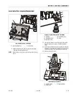
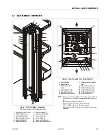
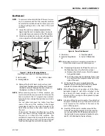
8.
At the top of the mast,
(See Figure 6-5.) - Item 2)
the cylinder rod for hydraulic cylinder #3 is
attached to platform mast section cross support
with a bolt and nut through a detent on the side
of the rod. Remove the locking nut from the hex
head bolt holding the cylinder rod in place to
the mast cross support. Remove the bolt from
the cross support. It may be necessary to lift or
lower slightly on the platform assembly with the
lifting strap to remove the bolt.
9.
Also at the top of the mast opening,
6-5.) - Item 3)
remove the two (2) bolts and nuts
attaching the power-trak cable guide to the plat-
form rail for the AC receptacle and platform con-
trol station electrical cables.
NOTE:
It may be necessary to pull down or push up on the
rear of the platform to keep the platform level while
lifting it off of the mast assembly.
Figure 6-4. Extending Mast Unpowered
1.
Sling Position -1
2.
Sling Position - 2
3.
Lifting Ring/Hook
4.
Manual Descent Valve Location
Содержание 1230ES
Страница 1: ...AS NZS Service and Maintenance Manual Model s 1230ES P N 3121222 June 22 2017 ...
Страница 2: ...NOTES ...
Страница 24: ...SECTION 1 MACHINE SPECIFICATIONS 1 12 JLG Lift 3121222 NOTES ...
Страница 32: ...SECTION 2 GENERAL SERVICE INFORMATION 2 8 JLG Lift 3121222 NOTES ...
Страница 78: ...SECTION 4 BASE COMPONENTS 4 40 JLG Lift 3121222 NOTES ...
Страница 104: ...SECTION 5 CONTROL COMPONENTS 5 26 JLG Lift 3121222 NOTES ...
Страница 158: ...SECTION 8 DIAGNOSTIC TROUBLE CODES 8 22 JLG Lift 3121222 NOTES ...
Страница 169: ...SECTION 9 GENERAL ELECTRICAL INFORMATION SCHEMATICS 3121222 JLG Lift 9 11 Figure 9 5 Connector Installation ...
Страница 198: ...SECTION 9 GENERAL ELECTRICAL INFORMATION SCHEMATICS 9 40 JLG Lift 3121222 ...
Страница 199: ...SECTION 9 GENERAL ELECTRICAL INFORMATION SCHEMATICS 3121222 JLG Lift 9 41 ...
Страница 200: ...SECTION 9 GENERAL ELECTRICAL INFORMATION SCHEMATICS 9 42 JLG Lift 3121222 ...
Страница 202: ...SECTION 9 GENERAL ELECTRICAL INFORMATION SCHEMATICS 9 44 JLG Lift 3121222 NOTES ...


