


SECTION 4 - BASE COMPONENTS
3121222
– JLG Lift –
4-33
Hydraulic System Pressure Settings
Perform final hydraulic pressure setting with oil at normal
operating temperature. If pressure is set when cold, func-
tion may not operate properly after oil has warmed.
Turning relief adjustment screw
clockwise - increases
pressure
, turning adjustment screw
counterclockwise -
decreases pressure
. DO NOT EXCEED MAXIMUM PRES-
SURE SETTINGS
.
1.
To check the lift pressure, attach pressure gauge
to the check port on top of the valve body.
To check steer pressure remove either the left or
right steer hose fitting on the valve body and
plumb a pressure gauge at that point.
2.
Power up machine, warm up oil to normal oper-
ating temperature.
3.
Check initial pressure for each function, lift and
steering.
4.
Adjust pressure relief according to settings
shown in Table 4-2. Lift pressure setting must be
adjusted to raise the maximum capacity allowed
in the platform with the mast fully extended. Do
not exceed the MAXIMUM pressure settings.
Table 4-2. Hydraulic Pressure Settings
1230ES
MAXIMUM PRESSURE SETTING
Main
1600 PSI (110 Bar)
Steer - Left/Right
1250 PSI (86 Bar)
Component
Coil Rating
Lift-Up Solenoid
28 Ohm
Steer - Left/Right Solenoid
33 Ohm
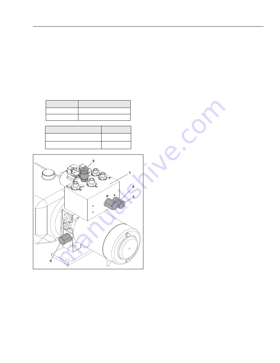
Figure 4-13. Relief Pressure Setting Locations
1.
Pump Valve Body
2.
Steering Right Pressure Relief
3.
Steering Left Pressure Relief
4.
Main Pressure Relief
5.
Pressure Gauge Check Port
Содержание 1230ES
Страница 1: ...AS NZS Service and Maintenance Manual Model s 1230ES P N 3121222 June 22 2017 ...
Страница 2: ...NOTES ...
Страница 24: ...SECTION 1 MACHINE SPECIFICATIONS 1 12 JLG Lift 3121222 NOTES ...
Страница 32: ...SECTION 2 GENERAL SERVICE INFORMATION 2 8 JLG Lift 3121222 NOTES ...
Страница 78: ...SECTION 4 BASE COMPONENTS 4 40 JLG Lift 3121222 NOTES ...
Страница 104: ...SECTION 5 CONTROL COMPONENTS 5 26 JLG Lift 3121222 NOTES ...
Страница 158: ...SECTION 8 DIAGNOSTIC TROUBLE CODES 8 22 JLG Lift 3121222 NOTES ...
Страница 169: ...SECTION 9 GENERAL ELECTRICAL INFORMATION SCHEMATICS 3121222 JLG Lift 9 11 Figure 9 5 Connector Installation ...
Страница 198: ...SECTION 9 GENERAL ELECTRICAL INFORMATION SCHEMATICS 9 40 JLG Lift 3121222 ...
Страница 199: ...SECTION 9 GENERAL ELECTRICAL INFORMATION SCHEMATICS 3121222 JLG Lift 9 41 ...
Страница 200: ...SECTION 9 GENERAL ELECTRICAL INFORMATION SCHEMATICS 9 42 JLG Lift 3121222 ...
Страница 202: ...SECTION 9 GENERAL ELECTRICAL INFORMATION SCHEMATICS 9 44 JLG Lift 3121222 NOTES ...


