SECTION 6 - MAST COMPONENTS
6-12
– JLG Lift –
3121222
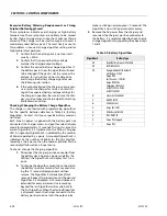
Multi-Stage Hydraulic Cylinder - Cylinder Bleeding
Procedure
THE THREE STAGE CYLINDER MUST BE BLED IN THE SEQUENCE OF CYL.
#1, THEN CYL. #2, THEN CYL. #3.
1.
First check that hydraulic oil level is between the
min./max. markings on the side of the pump res-
ervoir.
2.
In the platform, if necessary, remove the mast
cover from the top of the mast assembly.
3.
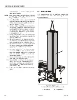
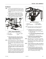
Place the proper size 90° angled line wrench on
the bleeder valve of cylinder #1.
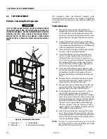
for orientation of bleeder valves.
4.
Attach a plastic tube to the bleeder valve on cyl-
inder #1, use a tube long enough to hang over
the side of the mast assembly and place the
loose end into a container to catch the hydraulic
fluid.
5.
Power up the machine.
6.
Loosen the bleeder valve on the cylinder being
bled. Be certain the other end of the bleeder
tube is in the catch container.
7.
Set the platform control station to platform lift
mode and push the joystick to lift the platform.
Do not allow the platform to lift to far off the
stowed position, re-lower and lift again if neces-
sary.
8.
Watch the bleeder tube, when a constant flow of
oil (no bubbles) is visible, close the bleeder valve.
9.
Remove the bleeder tube and line wrench and
move to the next cylinder in sequence. Repeat
steps 6 through 8 until all three cylinders are
bleed.
10.
It is recommended that the platform be cycled
up and down a few full lifts. Then repeat step 1.
11.
Finally repeat steps 6 through 10 again then cyl-
inder bleeding is completed.
Mast Installation Completion
Once mast is installed and properly bled to remove the air
from the hydraulic lift system, wipe off any excess hydrau-
lic oil from accessible surfaces of the mast and hydraulic
cylinder. If necessary, check the lift system hydraulic pres-
sure setting. Cycle the mast up and down a few times then
check at the top and bottom of the mast for any hydraulic
oil leaks.
Содержание 1230ES
Страница 1: ...AS NZS Service and Maintenance Manual Model s 1230ES P N 3121222 June 22 2017 ...
Страница 2: ...NOTES ...
Страница 24: ...SECTION 1 MACHINE SPECIFICATIONS 1 12 JLG Lift 3121222 NOTES ...
Страница 32: ...SECTION 2 GENERAL SERVICE INFORMATION 2 8 JLG Lift 3121222 NOTES ...
Страница 78: ...SECTION 4 BASE COMPONENTS 4 40 JLG Lift 3121222 NOTES ...
Страница 104: ...SECTION 5 CONTROL COMPONENTS 5 26 JLG Lift 3121222 NOTES ...
Страница 158: ...SECTION 8 DIAGNOSTIC TROUBLE CODES 8 22 JLG Lift 3121222 NOTES ...
Страница 169: ...SECTION 9 GENERAL ELECTRICAL INFORMATION SCHEMATICS 3121222 JLG Lift 9 11 Figure 9 5 Connector Installation ...
Страница 198: ...SECTION 9 GENERAL ELECTRICAL INFORMATION SCHEMATICS 9 40 JLG Lift 3121222 ...
Страница 199: ...SECTION 9 GENERAL ELECTRICAL INFORMATION SCHEMATICS 3121222 JLG Lift 9 41 ...
Страница 200: ...SECTION 9 GENERAL ELECTRICAL INFORMATION SCHEMATICS 9 42 JLG Lift 3121222 ...
Страница 202: ...SECTION 9 GENERAL ELECTRICAL INFORMATION SCHEMATICS 9 44 JLG Lift 3121222 NOTES ...

