background image

www.javad.com

www.javad.com

37

36

Base/Rover Setup

Base/Rover Setup

Tapping the 

UHF

 or 

FH915 Configuration

 button will 

trigger an immediate search for the radio via Bluetooth 

between the Base and the radio.  If a Bluetooth enabled 

radio is not found to be currently paired to the Base, you 

will be prompted to pair the radio.  This can be done via 

the Bluetooth option if the radio is currently not paired to a 

base.  If the radio was previously paired to a base, it would 

need to be unpaired before it could be paired to another 

base through the Bluetooth option.  The USB option can 

be used to pair a radio that is currently paired to a different 

base by connecting the ratio to the TRIUMPH-LS through 

the USB port.

For UHF radios the parameters shown to the right need 

to be configured.  The 

Frequency

  should be one of your 

FCC licensed (US users) frequencies.  A channel with 

little interference should be chosen.  From the 

Frequency


selection screen you can 

Scan

 the displayed channels to 

check the interference levels.
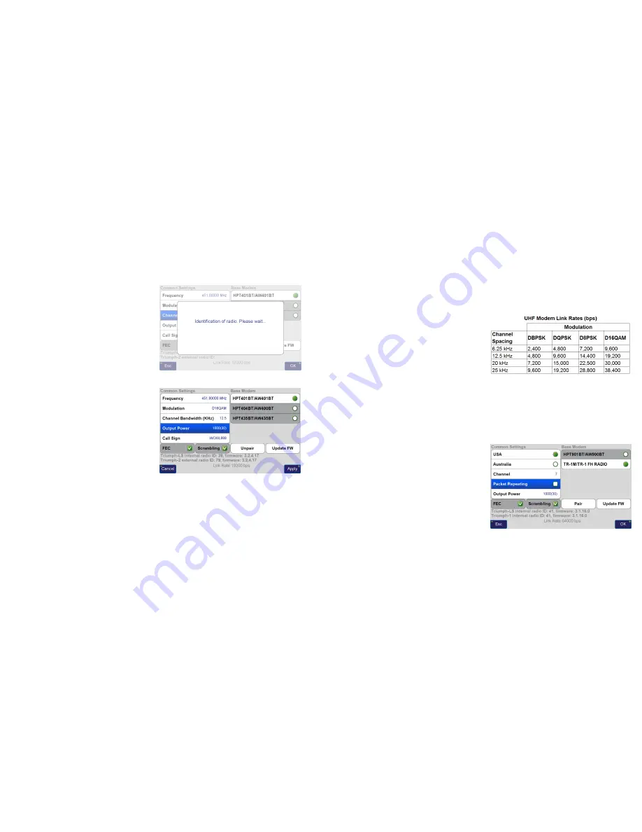
Modulation 

(the method the data is encoded in the radio 

signal) must be selected that has a sufficient link rate to 

transmit the corrections.  In the US 

Channel Bandwidth 

is


limited to 12.5 kHz the FCC and D16QAM modulation must 

be used with a 5 Hz correction rate (0.2 second broadcast 

period).  D8PSK modulation should be used if the radio is 

transmitting at 1 Hz.  Modulations with greater link rates 

have decreased receiver sensitivity to demodulate the 

signal and the downside to choosing modulations with 

higher link rates is that they are more subject to interference 

and data loss when the signal is weak.  Field test have found 

that D16QAM modulation decreases the working range 

of the radio approximately 20% as compared to DQPSK 

modulation.

Increasing the 

Output Power

 increases radio range but 

also increases radio power consumption.  With an antenna 

UHF Configuration

 Screen

height 4 m (13.1 ft), D16QAM modulation and a 1 watt 

output power, 5 Hz RTK corrections can have a stable range 

up to 4 km (2.5 miles) away when terrain obstacles do not 

block the signal.  A hill or ridge between the Base and Rover 

will greatly limit the range.  The FCC (US) allows up to 35 

watts ERP (Effective Radiated Power) to be transmitted.  If 

you have a HPT435BT radio set to output 35 watts and are 

using an antenna that isn’t a unity gain antenna, such as the 

5 dBd gain whip antenna, you aren’t in conformance with 

the FCC regulations and terms of your license.  

With the 5 

dBd gain whip antenna, an 

Output Power

 of 10 watts or less 

must be used to stay under 35 watts ERP

.

Your FCC assigned call sign should be entered in the 

Call 

Sign

 box.

The 

Unpair

 button is used to unpair the Bluetooth 

connection between the base and Rover.  This would only 

be necessary if you wish to pair a different radio to your 

Base.

Update FW

 checks and installs the latest radio firmware.  

FH915 SS


Radio Settings

With a

 FH915 SS


radio 

Packet Repeating

 must be disabled 

when using correction rates greater than 1 Hz.

In the US it may be best to operate on 

Channel

 7 to avoid 

interference.

Field test confirm 4 km (2.5 miles) as the range at which 

stable 5 Hz RTK can be achieved with a 

FH915 SS


radio with a 

4 m (13.1 ft) antenna height.  With 2 m you may achieve up to 

2 km (1.2 miles), but it is dependent upon the environment.

FH915 SS Configuration

 Screen

Содержание TRIUMPH-LS

Страница 1: ...Q U I C K S TA R T G U I D E TO T H E T R I U M P H L S W I T H J F I E L D 2 0 E Version 20160930...

Страница 2: ...to J Field read and understand the information in this manual before attempting to use J Field To obtain good results and RTK solutions it is most critical to understand the RTK Verification and Vali...

Страница 3: ...atus of the battery and internal temperatures Zoom In Advance to the next page screen Battery status LED Charge Status LED Check Used to open or select the current item box Home Press to return to the...

Страница 4: ...d lines CoGo Various CoGo Functions DPOS and CameraTools Setup Summary the setup profile name is displayed below Setup Configure the setup profiles Coordinate Systems lists all the system coordi nate...

Страница 5: ...Live Technical Support team members are listed in Support Live Technical Support You are also encouraged to submit your feedback and questions to the user s forum located at http support javad com Tur...

Страница 6: ...their respective signal strength tap on the WiFi icon in the top row of icons on the Home screen and then at the bottom of that screen tap on Network Select the desired access point tap on Connect ent...

Страница 7: ...Design Points Polylines and lines or Trajectories DPOS The DPOS button opens the DPOS screen that allows raw GNSS data to be submitted to the JAVAD Data Processing Service Base station data can be pro...

Страница 8: ...or names which contain the search string in the middle but do not begin or end with it looks for names which end with the search string Activating more than one switch combines the results activate an...

Страница 9: ...t your Region Country and type of coordinate system Select the appropriate HeightSystem Geoid InputEpochand Transformation A typical coordinate system configurations for a US State Place Coordinate Sy...

Страница 10: ...ns exist to enter a new factor as a Ratio or Ppm The Factors button will allow you to use the CoGo Scale Factor function to calculate a new scale factor if desired These settings will create an adjust...

Страница 11: ...re and Customize Screen Each J Field Project has a data db file stored in its project folder found in Internal Memory VS Data Maps All the pointsandlinesforaprojectarestoredinthisfile Bydefault the In...

Страница 12: ...nts listed if you completed the previous steps correctly Choose the desired account and press OK Mounting a Shared Network Folder Mounting a shared network folder allows files to be transfered to and...

Страница 13: ...le open the Data Exchange screen from the Home Screen 2 or from Files Data Exchange Data Exchange Screen Navigate to the location where your file is located using the to go up a directory and Open to...

Страница 14: ...with the description field being a merged field J Field s Code Attributes and Description fields These fields are merged together with the use of Sep 2 Separator 2 set to be a space By default fields...

Страница 15: ...ate and manage your own library of Codes alpha numeric textual assignments to points Codes can quickly be recalled from the Favorite Codes screen eliminating the need to type in a point description fo...

Страница 16: ...e Appendix A Creating a RTN Profile for detailed instructions on setting up a RTN Copy As creates a copy of the existing profile but prompts you to enter a new name for the new profile Setup Screen Ad...

Страница 17: ...es a matching base station profile internally It then sends that base station profile to the base through the Bluetooth connection Before Base Rover Setup can be used a UHF or FH915 SS General Group r...

Страница 18: ...left panel opens the screen to configure the radio parameters RTCM 3 0 Min Format should be used to minimize the correction data that must be sent through the radio To use 5 Hz BEAST MODE the Broadcas...

Страница 19: ...e subject to interference and data loss when the signal is weak Field test have found that D16QAM modulation decreases the working range of the radio approximately 20 as compared to DQPSK modulation I...

Страница 20: ...an be submitted to DPOS and all the survey points from that base station session can be adjusted to their real coordinates so they are no longer based off an autonomous position The recording interval...

Страница 21: ...g received by the base and the rover the time required to acquire a fix is inversely proportional to the rate of the ambiguities are being processed By reducing the time for the RTK engines to fix wit...

Страница 22: ...of the project Here linework can be drawn on the map with the CAD functions and point data can be edited The View button opens a screen to configure what point attributes are displayed on the map and...

Страница 23: ...en How to Stop Screen Recommended Settings for Surveying Monuments in Multipath Environments with 5 Hz BEAST MODE Corrections What To Record presents options to automatically capture raw GNSS data cam...

Страница 24: ...tep will guarantee a bad solution is not allowed to be accepted From extensive testing in the worst of multipath environments a bad solution has yet to be accepted when Verify and Validate are enabled...

Страница 25: ...FIX Fixed FLT Float CDF WAAS Code Differential Float or STN Standalone solution types areindicated TapthisboxtoopentheRTKV6 screen Shortcut to the Review screen Correct for Tilts On Stakeout To be use...

Страница 26: ...tics of Phase 1 Restarts of Groups of Epochs outside the Confidence Guard during Phase 2 Coordinates of current position Current epoch count Time Duration is seconds between the first and last epoch c...

Страница 27: ...Screen with Expanded User Defined Buttons The User Defined Buttons are expanded by pressing the Action hardware button The most commonly used and recommend User Defined Button options are shown below...

Страница 28: ...rrected by surveying a point with known coordinates The known point could be a point previously surveyed with a base station setup in a different location This feature is useful for several scenarios...

Страница 29: ...se station data is automatically recorded when a base stationisstartedwithBase RoverSetup Afterdonesurveying connect to base in Base Rover Setup and choose Stop Base You will be prompted with several...

Страница 30: ...s the data Base Processing base and rover raw GNSS data are uploaded to DPOS and base rover vectors are then processed Base Shift base station data is processed with CORS data the base station coordin...

Страница 31: ...rizontal andVertical RMS The current radio button is selecting this column coordinate type for the base and associated rover points is KNOWN base station was started from a known coordinate If the bas...

Страница 32: ...he added points to M Local and apply the adjustment to the associated base and rover coordinates Processed Point Info Screen The M Local coordinate is the current coordinate 3 pairs of points exist in...

Страница 33: ...e of this point Once all the inputs have been entered you may tap the diagram to preview the results in the map If satisfied tap Create to create the resultant points Preview Screen of Cogo Direct The...

Страница 34: ...the bottom left corner of these boxes Press to switch the coordinates of P1 P2 Clicking on the right side of output boxes such as B Grid copies the value of the box into the selected clipboard box Re...

Страница 35: ...i Select screen is used to select the points to be shifted To select individual points in this screen use the Check Hardware button for easier selection of individual points Multi Select Screen Select...

Страница 36: ...the correction type Tap New to create a new RTN APN Access Point Name Enter a name for the new APN Select NTRIP Client as the APN Protocol Enter the Host Name TCP Port Username and Password provided b...

Страница 37: ...900 Rock Avenue San Jose CA 95131 USA Phone 1 408 770 1770 Fax 1 408 770 1799 www javad com Copyright JAVAD GNSS Inc 2016 All rights reserved No unauthorized duplication...

Отзывы: