background image

www.javad.com

www.javad.com

47

46

Collect

Collect

RTK Verification and Validation

It is very important that you read and understand the 

information about 

RTK Verification 

and

 Validation


contained in this manual.


Verify Settings

 Screen - Recommended Settings for Multipath 

Environments

When located in difficult environments and under tree 

canopy, all GNSS receivers are prone to give bad fixed 

solutions that may appear to be acceptable if they are not 

verified.  Existing methods to verify GNSS solutions include 

“dumping” the receiver, turning it upside down to cause the 

RTK engines to reset, and re-observing the point at a later 

time.

J-Field automates these processes with its built-in software 

features of 

Verify

 and 

Validate

.  

Verify

 automatically resets 

the RTK engines after every fixed epoch is collected in 

Phase-1


of its process.  Epochs are placed into 

Groups

 or 

buckets during 

Phase-1

.  Once a 

Group

 has met the required 

Confidence Level

 and 

Minimum Phase-1 Duration 

(time 

between the first and last epoch in that group), 

Phase-1

 is 

complete.  

The 

Confidence Guard 

(

CG)

 determines the size of the 

Group


or bucket.  Each 

Group

 contains all the epochs located 

within a specified radius (the 

CG

 value) from its center and 

new 

Groups

 are created as necessary so that all epochs 

fall into at least one 

Group

.  Each 

Group

 has its own 

Epoch 

Counter

Confidence Level

 and 

Elapsed Time

.  A point may 

fall into more than one group.  The groups are sorted from 

best to last by the sum of their 

Time

 and 

Confidence

 with the 

current best group being shown within [ ] and others within 

( ).  

Show on the Screen

 specifies how many groups will be 

displayed on the plots on the screen.  There is no limit to the 

number of groups that will be stored internally but only up 

to the best 6 will be displayed on the screen.

During 

Phase-2

 the engines are not reset and solutions 

which are located inside the 

CG

 of the selected 

Group

 are 

added to that 

Group

 for the remaining number of epochs 

that user has requested (

Epoch Number

EN

) in the 

How to 

Stop

 screen.  Epochs which are outside the 

CG

 of the selected 

Group

 will be stored in a new (or previously created) group; 

the RTK engines are reset if the epoch falls outside a sphere 

with a radius twice that of the 

CG

.  If the number of epochs 

falling outside of the current group reaches 30% of epochs 

collected so far, the process will revert back to 

Phase-1

 and 

the 

Confidence Level 

of the current group will be reset to 

0.  Previously created groups will remain intact and once 

an existing or previously created group meets the 

Phase-1 

criteria, it will pass to 

Phase-2

.

Validation

 is the final phase of the process.  With this 

feature enabled the RTK engines will reset one final time 

at the end of the observation and collect 10 additional 

epochs.  Allowing sufficient time between 

Phase-1

 and 

the final 

Validation

 step will guarantee a bad solution is 

not allowed to be accepted.  From extensive testing in the 

worst of multipath environments, a bad solution has yet 

to be accepted when 

Verify

 and 

Validate

 are enabled with 

Minimum Duration

 of

 least 180 seconds.  This will ensure 

that at least two separate fixed initiations are acquired at 

least 3 minutes apart.  

Having at least 2 fixed initiations in 

agreement and acquired at least 2 to 3 minutes apart has 

been found to be the critical requirement to ensure that 

bad fixed initiations are not accepted.

  In high multipath 

environments the Boundary Action Profile should be used 

to meet this requirement and guarantee a good initiation.  

You must let entire collection process complete.

Confidence Level

 and 

Consistency Level

 are counters; the 

Confidence Level

 of a group increments each time an epoch 

with a new RTK initiation (Fix) is collected.  It increments by 

values of 1, 1.25, 1.5, 1.75, 2.0, or 2.5 for 1 to 6 fixed engines, 

respectively.  The 

Consistency Level 

of a group increments 

with every epoch collected by values of 0, 0.1, 0.25, 0.5, 1.0, 

and 1.5 for 1 to 6 fixed engines.  The set 

Consistency Level 

must be met before 

Phase-2 

is allowed to end

.

If high accuracy is needed in areas of high multipath and 

areas with limited views of open sky (under full tree canopy 

and urban canyon environments), longer observations 

will improve accuracy.  Repeated observation can also 

be performed later (1 hour or more is recommended) to 

improve accuracy.  These repeated points can then be 

averaged together with the 

Average

 function found in 

Cogo 

Tools 

or with the

 Cluster Averaging 

function.

Recommended Collection Settings & 

Default Action Profiles

Boundary Action Profile

 - To be used for control and 

boundary shots and in high multipath environments (under 

tree canopy, next to buildings, etc.)


Š

Start with Start Button


Š

Stop After: 100 epochs


Š

Minimum Duration: 120 seconds (increasing this 

to 180 is preferred in bad locations for additional 

protection from accepting points with bad fixed 

initiations and for better post-processing results)


Š

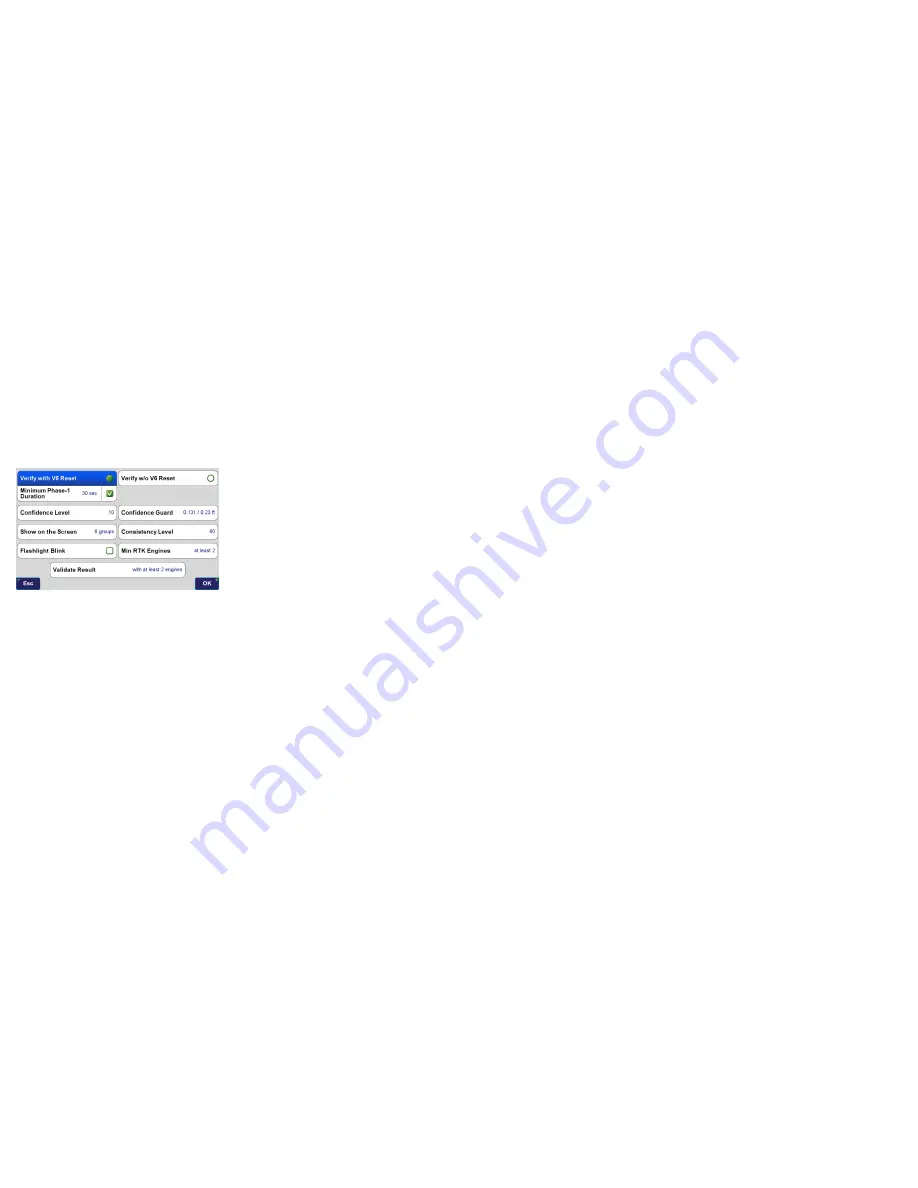
Minimum Phase-1 Duration: 30 seconds


Š

Verify with V6 Reset


Š

Confidence Level: 10


Š

Consistency Level: 10


Š

Min RTK Engines: At least 2


Š

Validate Result: with at least 2 engines


Š

Correct for Tilts: Off (Rover pole must be plumbed)

Precise Topo 

- To be used for topographic shots where some 

multipath may be present.  The receiver should still have at 

least a 50% clear view of the open sky.


Š

Start with Start Button


Š

Stop After: 10 epochs


Š

Minimum Duration: 10 seconds


Š

Verify with V6 Reset


Š

Confidence Level: 5


Š

Consistency Counter: 10


Š

Min RTK Engines: At least 2


Š

Validate Result: with at least 2 engines


Š

Correct for Tilts: Off

Quick Topo 

- To be used for rapid topographic shots in open 

sky environments.  If it is difficult to obtain 5 engine fixed, 

the environment may not be well suited for this profile and 

the 

Precise Topo

 profile should be used.


Š

Start with Start Button or Start When Tilted


Š

Stop After: 2 epochs


Š

Verify without V6 Reset


Š

Consistency Level: 0


Š

Min RTK Engines: At least 5

Содержание TRIUMPH-LS

Страница 1: ...Q U I C K S TA R T G U I D E TO T H E T R I U M P H L S W I T H J F I E L D 2 0 E Version 20160930...

Страница 2: ...to J Field read and understand the information in this manual before attempting to use J Field To obtain good results and RTK solutions it is most critical to understand the RTK Verification and Vali...

Страница 3: ...atus of the battery and internal temperatures Zoom In Advance to the next page screen Battery status LED Charge Status LED Check Used to open or select the current item box Home Press to return to the...

Страница 4: ...d lines CoGo Various CoGo Functions DPOS and CameraTools Setup Summary the setup profile name is displayed below Setup Configure the setup profiles Coordinate Systems lists all the system coordi nate...

Страница 5: ...Live Technical Support team members are listed in Support Live Technical Support You are also encouraged to submit your feedback and questions to the user s forum located at http support javad com Tur...

Страница 6: ...their respective signal strength tap on the WiFi icon in the top row of icons on the Home screen and then at the bottom of that screen tap on Network Select the desired access point tap on Connect ent...

Страница 7: ...Design Points Polylines and lines or Trajectories DPOS The DPOS button opens the DPOS screen that allows raw GNSS data to be submitted to the JAVAD Data Processing Service Base station data can be pro...

Страница 8: ...or names which contain the search string in the middle but do not begin or end with it looks for names which end with the search string Activating more than one switch combines the results activate an...

Страница 9: ...t your Region Country and type of coordinate system Select the appropriate HeightSystem Geoid InputEpochand Transformation A typical coordinate system configurations for a US State Place Coordinate Sy...

Страница 10: ...ns exist to enter a new factor as a Ratio or Ppm The Factors button will allow you to use the CoGo Scale Factor function to calculate a new scale factor if desired These settings will create an adjust...

Страница 11: ...re and Customize Screen Each J Field Project has a data db file stored in its project folder found in Internal Memory VS Data Maps All the pointsandlinesforaprojectarestoredinthisfile Bydefault the In...

Страница 12: ...nts listed if you completed the previous steps correctly Choose the desired account and press OK Mounting a Shared Network Folder Mounting a shared network folder allows files to be transfered to and...

Страница 13: ...le open the Data Exchange screen from the Home Screen 2 or from Files Data Exchange Data Exchange Screen Navigate to the location where your file is located using the to go up a directory and Open to...

Страница 14: ...with the description field being a merged field J Field s Code Attributes and Description fields These fields are merged together with the use of Sep 2 Separator 2 set to be a space By default fields...

Страница 15: ...ate and manage your own library of Codes alpha numeric textual assignments to points Codes can quickly be recalled from the Favorite Codes screen eliminating the need to type in a point description fo...

Страница 16: ...e Appendix A Creating a RTN Profile for detailed instructions on setting up a RTN Copy As creates a copy of the existing profile but prompts you to enter a new name for the new profile Setup Screen Ad...

Страница 17: ...es a matching base station profile internally It then sends that base station profile to the base through the Bluetooth connection Before Base Rover Setup can be used a UHF or FH915 SS General Group r...

Страница 18: ...left panel opens the screen to configure the radio parameters RTCM 3 0 Min Format should be used to minimize the correction data that must be sent through the radio To use 5 Hz BEAST MODE the Broadcas...

Страница 19: ...e subject to interference and data loss when the signal is weak Field test have found that D16QAM modulation decreases the working range of the radio approximately 20 as compared to DQPSK modulation I...

Страница 20: ...an be submitted to DPOS and all the survey points from that base station session can be adjusted to their real coordinates so they are no longer based off an autonomous position The recording interval...

Страница 21: ...g received by the base and the rover the time required to acquire a fix is inversely proportional to the rate of the ambiguities are being processed By reducing the time for the RTK engines to fix wit...

Страница 22: ...of the project Here linework can be drawn on the map with the CAD functions and point data can be edited The View button opens a screen to configure what point attributes are displayed on the map and...

Страница 23: ...en How to Stop Screen Recommended Settings for Surveying Monuments in Multipath Environments with 5 Hz BEAST MODE Corrections What To Record presents options to automatically capture raw GNSS data cam...

Страница 24: ...tep will guarantee a bad solution is not allowed to be accepted From extensive testing in the worst of multipath environments a bad solution has yet to be accepted when Verify and Validate are enabled...

Страница 25: ...FIX Fixed FLT Float CDF WAAS Code Differential Float or STN Standalone solution types areindicated TapthisboxtoopentheRTKV6 screen Shortcut to the Review screen Correct for Tilts On Stakeout To be use...

Страница 26: ...tics of Phase 1 Restarts of Groups of Epochs outside the Confidence Guard during Phase 2 Coordinates of current position Current epoch count Time Duration is seconds between the first and last epoch c...

Страница 27: ...Screen with Expanded User Defined Buttons The User Defined Buttons are expanded by pressing the Action hardware button The most commonly used and recommend User Defined Button options are shown below...

Страница 28: ...rrected by surveying a point with known coordinates The known point could be a point previously surveyed with a base station setup in a different location This feature is useful for several scenarios...

Страница 29: ...se station data is automatically recorded when a base stationisstartedwithBase RoverSetup Afterdonesurveying connect to base in Base Rover Setup and choose Stop Base You will be prompted with several...

Страница 30: ...s the data Base Processing base and rover raw GNSS data are uploaded to DPOS and base rover vectors are then processed Base Shift base station data is processed with CORS data the base station coordin...

Страница 31: ...rizontal andVertical RMS The current radio button is selecting this column coordinate type for the base and associated rover points is KNOWN base station was started from a known coordinate If the bas...

Страница 32: ...he added points to M Local and apply the adjustment to the associated base and rover coordinates Processed Point Info Screen The M Local coordinate is the current coordinate 3 pairs of points exist in...

Страница 33: ...e of this point Once all the inputs have been entered you may tap the diagram to preview the results in the map If satisfied tap Create to create the resultant points Preview Screen of Cogo Direct The...

Страница 34: ...the bottom left corner of these boxes Press to switch the coordinates of P1 P2 Clicking on the right side of output boxes such as B Grid copies the value of the box into the selected clipboard box Re...

Страница 35: ...i Select screen is used to select the points to be shifted To select individual points in this screen use the Check Hardware button for easier selection of individual points Multi Select Screen Select...

Страница 36: ...the correction type Tap New to create a new RTN APN Access Point Name Enter a name for the new APN Select NTRIP Client as the APN Protocol Enter the Host Name TCP Port Username and Password provided b...

Страница 37: ...900 Rock Avenue San Jose CA 95131 USA Phone 1 408 770 1770 Fax 1 408 770 1799 www javad com Copyright JAVAD GNSS Inc 2016 All rights reserved No unauthorized duplication...

Отзывы: