background image

www.javad.com

www.javad.com

43

42

Collect

Collect

which opens a screen to configure the collection settings 

for points.  The RTK Verification and Validation settings are 

configured from 

Action Setup

 screen.

Collect Prepare 

Screen

Pressing the 

Action

 hardware button or 

Next


from the 

Collect Prepare

 screen opens the 

Collect Action

 screen. 

Collect

Pressing the 

Collect

 button 

opens the 

Collect Prepare


screen; pressing 

Collect


hardware button twice 

will open the 

Collect Action


screen.

In the 

Collect Prepare

 screen, the 

Project

Page

Coordinate


System

ShapeTag

Code

Code


Attributes

Point


Name

Point


Description

Antenna


Height

 and collection settings can be 

setup before beginning data collection for a point.

When collecting points, it is recommended to use the 

Code and Code Attributes to store information about the 

point being collected.  The 

Description

 field can then be 

reserved for entering additional information about the 

point.  When exporting point coordinates in Text/CSV 

format, these three fields can be merged into one field so 

that surveying software can import data with the traditional 

“Name,N,E,H,Description” format but with the description 

being the combination of J-Field’s 

Code

Code


Attributes

 and 

Point


Descriptions

 fields.

The 

Review

 buttons opens the 

Review

 screen which is a map 

of the project.  Here linework can be drawn on the map with 

the CAD functions and point data can be edited.

The 

View

 button opens a screen to configure what point 

attributes are displayed on the map and allows some 

graphical parameters to be customized.

To the right of the View button is the 

Action Setup

 button 

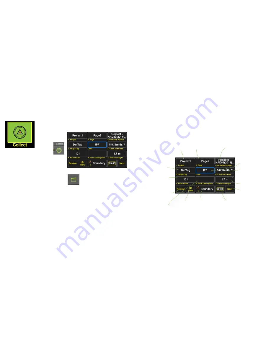
Screen Anatomy - Collect Prepare Screen

The 

Review

 buttons opens the 

Review


screen which is a map of the project.  

Here linework can be drawn on the map 

with the CAD functions and point data 

can be edited.

The 

View

 button opens a 

screen to configure what point 

attributes are displayed on the 

map and allows some graphical 

parameters to be customized.

The 

Project

 button displays the name 

of the current 

Project

.  Tap it to open 

an existing 

Project

, to create a new 

Project

, or to edit the current 

Project’s


name or coordinate system. 

The 

Page

 button displays the name of 

the current 

Page

.  Tap it  to open the 

Pages

 screen and set the current 

Page

turn on or off 

Pages

 or edit a 

Page


Name or coordinate system.  

The 

Coordinate System

 button displays 

the name of the coordinate system for 

the current 

Page

.  Tap it to change this 

coordinate system.  

The 

Code

 button displays the name of 

the 

Code 

that will be assigned to the 

next surveyed point.  Tap it to choose 

a new 

Code 

from your list of 

Favorite 

Codes

.  

Up to five variable 

Code Attributes


fields can be used be used to store 

additional information about a point 

with this box.

ShapeTags

 can be assigned to points 

during data collection to enable the 

automated drawing of lines between 

points with like 

ShapeTags

.   “DefTag” 

is the default 

ShapeTag

 and does not 

create lines between points. 

Edit the height of the ARP (Antenna 

Reference Point).

Takes you to the 

Action

 screen

The 

Point Name

 button displays the 

name that will be assigned to the 

next surveyed point.  After a point is 

surveyed it will increment to the next 

available name.

Displays the estimated remaining 

battery life and is a shortcut to 

the 

Battery


Status

 screen

Displays the current 

Action Group 

pro-

file name


group and opens the 

Action 

Setup

 screen.  The rover icon displays 

whether tilt corrections are enabled 

or not (disabled above).  The clock icon 

indicates the 

How to Stop?

 setting has 

been set to a fixed number of epochs.

Use the 

Point Description

 field to store 

additional information about the point.

Содержание TRIUMPH-LS

Страница 1: ...Q U I C K S TA R T G U I D E TO T H E T R I U M P H L S W I T H J F I E L D 2 0 E Version 20160930...

Страница 2: ...to J Field read and understand the information in this manual before attempting to use J Field To obtain good results and RTK solutions it is most critical to understand the RTK Verification and Vali...

Страница 3: ...atus of the battery and internal temperatures Zoom In Advance to the next page screen Battery status LED Charge Status LED Check Used to open or select the current item box Home Press to return to the...

Страница 4: ...d lines CoGo Various CoGo Functions DPOS and CameraTools Setup Summary the setup profile name is displayed below Setup Configure the setup profiles Coordinate Systems lists all the system coordi nate...

Страница 5: ...Live Technical Support team members are listed in Support Live Technical Support You are also encouraged to submit your feedback and questions to the user s forum located at http support javad com Tur...

Страница 6: ...their respective signal strength tap on the WiFi icon in the top row of icons on the Home screen and then at the bottom of that screen tap on Network Select the desired access point tap on Connect ent...

Страница 7: ...Design Points Polylines and lines or Trajectories DPOS The DPOS button opens the DPOS screen that allows raw GNSS data to be submitted to the JAVAD Data Processing Service Base station data can be pro...

Страница 8: ...or names which contain the search string in the middle but do not begin or end with it looks for names which end with the search string Activating more than one switch combines the results activate an...

Страница 9: ...t your Region Country and type of coordinate system Select the appropriate HeightSystem Geoid InputEpochand Transformation A typical coordinate system configurations for a US State Place Coordinate Sy...

Страница 10: ...ns exist to enter a new factor as a Ratio or Ppm The Factors button will allow you to use the CoGo Scale Factor function to calculate a new scale factor if desired These settings will create an adjust...

Страница 11: ...re and Customize Screen Each J Field Project has a data db file stored in its project folder found in Internal Memory VS Data Maps All the pointsandlinesforaprojectarestoredinthisfile Bydefault the In...

Страница 12: ...nts listed if you completed the previous steps correctly Choose the desired account and press OK Mounting a Shared Network Folder Mounting a shared network folder allows files to be transfered to and...

Страница 13: ...le open the Data Exchange screen from the Home Screen 2 or from Files Data Exchange Data Exchange Screen Navigate to the location where your file is located using the to go up a directory and Open to...

Страница 14: ...with the description field being a merged field J Field s Code Attributes and Description fields These fields are merged together with the use of Sep 2 Separator 2 set to be a space By default fields...

Страница 15: ...ate and manage your own library of Codes alpha numeric textual assignments to points Codes can quickly be recalled from the Favorite Codes screen eliminating the need to type in a point description fo...

Страница 16: ...e Appendix A Creating a RTN Profile for detailed instructions on setting up a RTN Copy As creates a copy of the existing profile but prompts you to enter a new name for the new profile Setup Screen Ad...

Страница 17: ...es a matching base station profile internally It then sends that base station profile to the base through the Bluetooth connection Before Base Rover Setup can be used a UHF or FH915 SS General Group r...

Страница 18: ...left panel opens the screen to configure the radio parameters RTCM 3 0 Min Format should be used to minimize the correction data that must be sent through the radio To use 5 Hz BEAST MODE the Broadcas...

Страница 19: ...e subject to interference and data loss when the signal is weak Field test have found that D16QAM modulation decreases the working range of the radio approximately 20 as compared to DQPSK modulation I...

Страница 20: ...an be submitted to DPOS and all the survey points from that base station session can be adjusted to their real coordinates so they are no longer based off an autonomous position The recording interval...

Страница 21: ...g received by the base and the rover the time required to acquire a fix is inversely proportional to the rate of the ambiguities are being processed By reducing the time for the RTK engines to fix wit...

Страница 22: ...of the project Here linework can be drawn on the map with the CAD functions and point data can be edited The View button opens a screen to configure what point attributes are displayed on the map and...

Страница 23: ...en How to Stop Screen Recommended Settings for Surveying Monuments in Multipath Environments with 5 Hz BEAST MODE Corrections What To Record presents options to automatically capture raw GNSS data cam...

Страница 24: ...tep will guarantee a bad solution is not allowed to be accepted From extensive testing in the worst of multipath environments a bad solution has yet to be accepted when Verify and Validate are enabled...

Страница 25: ...FIX Fixed FLT Float CDF WAAS Code Differential Float or STN Standalone solution types areindicated TapthisboxtoopentheRTKV6 screen Shortcut to the Review screen Correct for Tilts On Stakeout To be use...

Страница 26: ...tics of Phase 1 Restarts of Groups of Epochs outside the Confidence Guard during Phase 2 Coordinates of current position Current epoch count Time Duration is seconds between the first and last epoch c...

Страница 27: ...Screen with Expanded User Defined Buttons The User Defined Buttons are expanded by pressing the Action hardware button The most commonly used and recommend User Defined Button options are shown below...

Страница 28: ...rrected by surveying a point with known coordinates The known point could be a point previously surveyed with a base station setup in a different location This feature is useful for several scenarios...

Страница 29: ...se station data is automatically recorded when a base stationisstartedwithBase RoverSetup Afterdonesurveying connect to base in Base Rover Setup and choose Stop Base You will be prompted with several...

Страница 30: ...s the data Base Processing base and rover raw GNSS data are uploaded to DPOS and base rover vectors are then processed Base Shift base station data is processed with CORS data the base station coordin...

Страница 31: ...rizontal andVertical RMS The current radio button is selecting this column coordinate type for the base and associated rover points is KNOWN base station was started from a known coordinate If the bas...

Страница 32: ...he added points to M Local and apply the adjustment to the associated base and rover coordinates Processed Point Info Screen The M Local coordinate is the current coordinate 3 pairs of points exist in...

Страница 33: ...e of this point Once all the inputs have been entered you may tap the diagram to preview the results in the map If satisfied tap Create to create the resultant points Preview Screen of Cogo Direct The...

Страница 34: ...the bottom left corner of these boxes Press to switch the coordinates of P1 P2 Clicking on the right side of output boxes such as B Grid copies the value of the box into the selected clipboard box Re...

Страница 35: ...i Select screen is used to select the points to be shifted To select individual points in this screen use the Check Hardware button for easier selection of individual points Multi Select Screen Select...

Страница 36: ...the correction type Tap New to create a new RTN APN Access Point Name Enter a name for the new APN Select NTRIP Client as the APN Protocol Enter the Host Name TCP Port Username and Password provided b...

Страница 37: ...900 Rock Avenue San Jose CA 95131 USA Phone 1 408 770 1770 Fax 1 408 770 1799 www javad com Copyright JAVAD GNSS Inc 2016 All rights reserved No unauthorized duplication...

Отзывы: