


Page 64
1998-2006 Edition
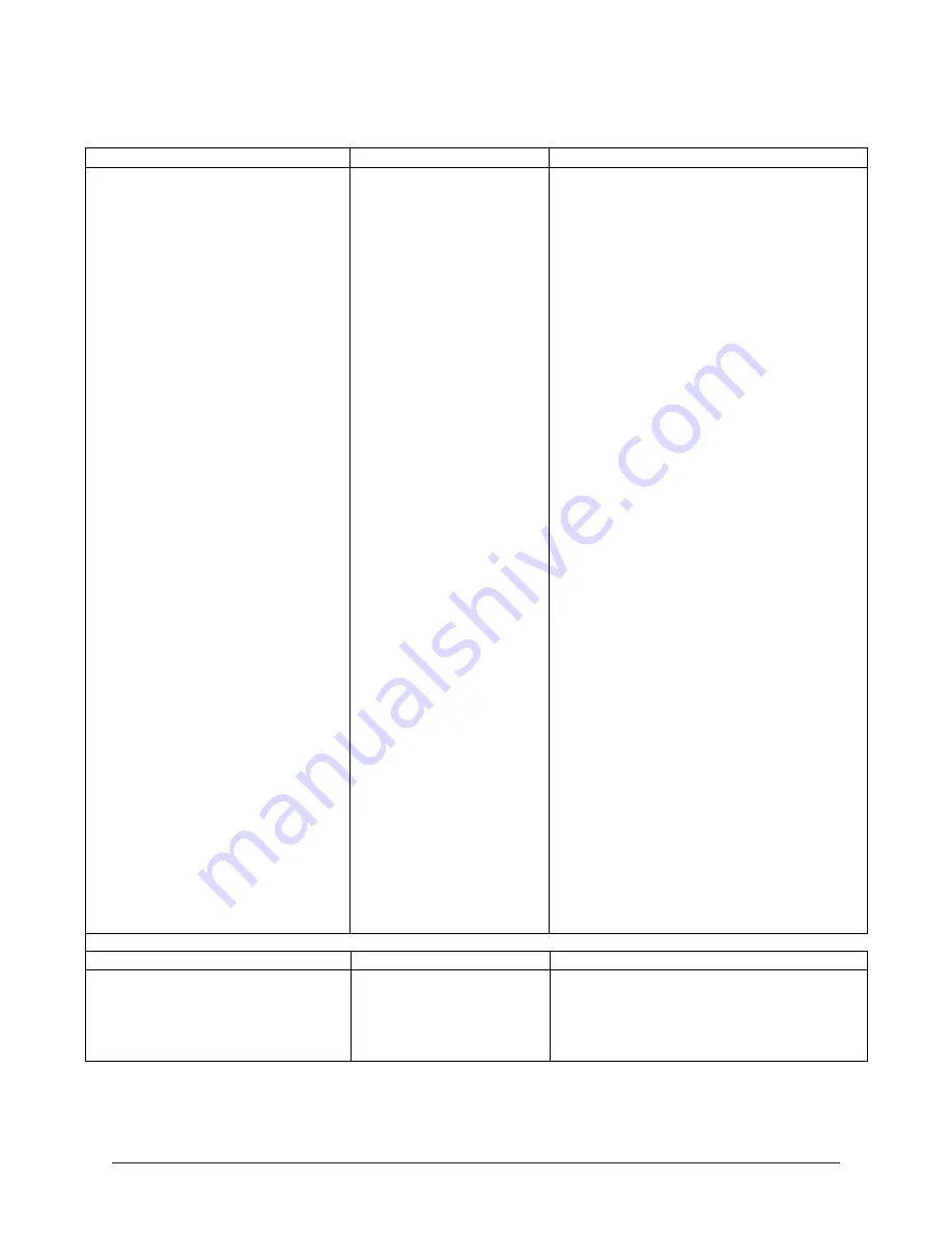
SYMPTOM #4
PROBABLE CAUSE
SOLUTION
The On/Off switch is ON, the green
1. Fuel Hopper is empty.
1. Fill Fuel Hopper with Pellets.
light is ON, the orange light is ON and
2. Auger is empty and
2. Let stove run in this condition for 5
the red light flashes but fuel does not
needs to be primed with
minutes or until pellets start to drop. Turn
feed into firepot.
pellets.
main power switch to OFF and wait 10
minutes. After 10 minutes, turn main
power switch to ON and wall thermostat to
ON.
3. Auger is "Jammed".
3. Empty Fuel Hopper of Pellets and check
for foreign object in the auger that is
Jamming the auger.
4. 250F (121ºC) high limit
4. Press red reset button on 250F (121ºC)
switch is stuck in the OFF
high limit switch. If pellets start to feed, then the
position.
stove had overheated and the 250F (121ºC)
switch turned off. If pellets still do not feed,
check continuity across the 250F (121ºC) switch
terminals. If continuous, see Probable
Cause #5 and check all auger circuit wiring
for faulty wires or loose connections.
5. Wires to vacuum switch
5. Turn On/Off switch to Off. Disconnect
are disconnected.
Vacuum hose at the connection under
Vacuum hose is plugged
combustion blower. Place hose end in
or Vacuum Switch is
mouth and create a high suction. Check
faulty.
for continuity across the two terminals on
the vacuum switch while maintaining
suction. If no continuity, check vacuum
hose for plug. If vacuum hose is not
plugged, vacuum switch is faulty. Replace
vacuum switch.
6. Dirty, weak or defective
6. If vacuum switch system checks OK,
combustion blower.
check the exhaust blower. Vacuum switch
will not turn on if exhaust blower is not
turning and creating proper vacuum. If
exhaust blower does not turn when direct
power is applied, replace exhaust blower
motor.
7. Plugged vent system.
7. Stove is designed so that a plugged vent
system will prevent vacuum switch from
turning ON. Check vent system for plugs.
Clean vent system. Entire stove and vent
system must be cleaned annually.
8. Wiring in stove is faulty
8. Check system wiring and auger motor.
or Auger motor is faulty
Connect auger motor to direct AC power.
or damaged.
If motor does not turn, motor is defective,
replace.
SYMPTOM #5
PROBABLE CAUSE
SOLUTION
Stove burns normally during the 12
minute Startup Cycle. After the 12
minutes, however, the fuel stops
feeding and the green Status light
flashes once every 2 seconds.
1. Stove is not warming up
sufficiently within the 12
minutes.
1. See Section X: Electrical System
Information in this manual. Specifically,
refer to Program Selection Information and
Control Board Program Parameters Table.
Содержание J1000B
Страница 2: ......
Страница 8: ...Page vi 1998 2006 Edition ...
Страница 16: ...Page 8 1998 2006 Edition ...
Страница 20: ...Page 12 1998 2006 Edition ...
Страница 36: ...Page 28 1998 2006 Edition ...
Страница 38: ...Inside the Room and Recessed in an Interior Chase Page 30 1998 2006 Edition Recessed in an Exterior Chase ...
Страница 39: ...Corner Installation Page 31 1998 2006 Edition Installation requires standoffs to maintain clearances ...
Страница 44: ...Page 36 1998 2006 Edition ...
Страница 45: ...Page 37 1998 2006 Edition ...
Страница 46: ...VIII 5 Jamestown Control Panel Page 38 1998 2006 Edition ...
Страница 61: ...Page 53 1998 2006 Edition ...
Страница 62: ...Page 54 1998 2006 Edition ...
Страница 63: ...Page 55 1998 2006 Edition ...
Страница 64: ...Page 56 1998 2006 Edition ...
Страница 69: ...Page 61 1998 2006 Edition ...
Страница 70: ...Page 62 1998 2006 Edition ...
Страница 79: ...Appendix A 3 1998 2006 Edition ...
Страница 80: ...Appendix A 4 1998 2006 Edition ...
Страница 81: ...Appendix A 5 1998 2006 Edition ...
Страница 82: ...Appendix A 6 1998 2006 Edition ...
Страница 84: ...Appendix B 2 1998 2006 Edition ...
Страница 86: ...APPENDIX D EXHAUST BLOWER ASSEMBLY MODEL J1000 Appendix D 1 1998 2006 Edition Complete Assembly is Part 07DAA ...
Страница 87: ...APPENDIX E AUGER MOTOR BRACKET INSTALLATION Appendix E 1 1998 2006 Edition ...
Страница 90: ...Appendix F 3 1998 2006 Edition ...
Страница 93: ...APPENDIX H J1000 CROSSFLOW FAN Part 07EEG Appendix H 1 1998 2006 Edition ...
Страница 94: ...APPENDIX I 1 EXHAUST BLOWER ASSEMBLY MODEL J1000 Appendix I 1 1998 2006 Edition ...
Страница 96: ...SERVICE RECORD DATE SERVICED BY DESCRIPTION ...